


Tactical Enforcer: Driller Shark (Sumo)
I was busying myself with this robot for the CNRG 2010 competition in Toronto, so I haven't been able to keep up to date on this website. However I am back now. This robot post is probably gonna be long cause I'm gonna post lots of pictures. For those of you that actually read my posts, I appreciate it. For those who don't, you can enjoy the pictures.
Like most of my sumos, I designed this one around the motors. I got some Maxon motors off ebay for cheap, however the length end to end was 55mm which kind of sucks for mini sumo.
Putting the motors end to end would yield a total length of 110mm, which puts me over the dimension limit. The only solution was to stagger the motors. Now that I had the motors and an idea of the layout, I set to work on the body.
In town here there is a plastic manufacturer. If you ask them nicely they will give you their offcuts and scraps for free. I managed to pick up this piece of UHMW which was the perfect size to make the body. I cut off a piece and drilled some holes by hand to mount the motors.
But as you can see, I suck at lining things up. So I made a CAD model and generated some gcode for the cnc. It did a better job of drilling the holes and they lined up perfectly.
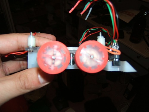
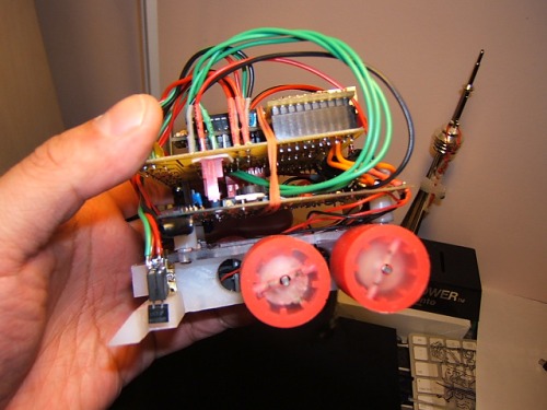
The next part I made was the wheels. I used the same method as I did for Blaster shark, but used polyurethane mold rubber instead of silicon. And as you can see it is more grippy.
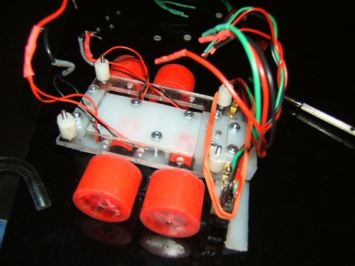
Next I milled out a mounting plate for the electronics and put it all together.
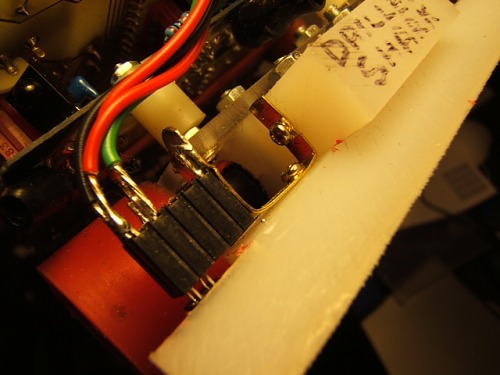
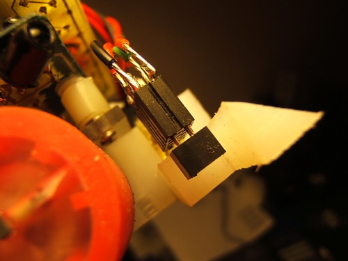
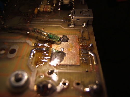
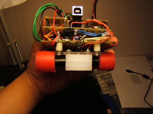
Its all starting to come together. I then milled a front scoop and attached the floor sensors. I used a similar method as Blaster shark and attached a 2 row header to a brass picture hanger hook, soldered wires to it, and inserted the sensor.
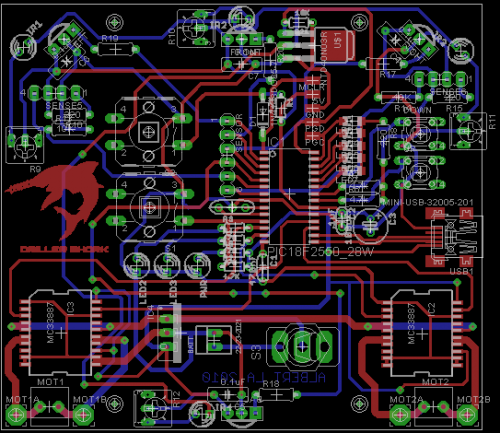
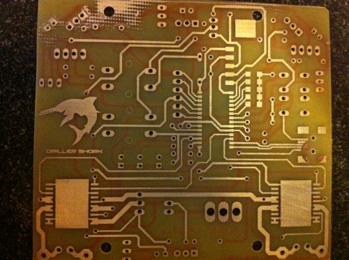
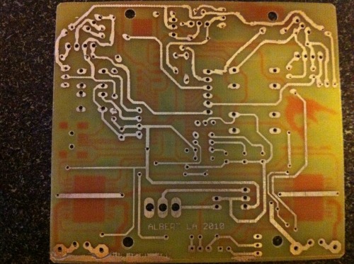
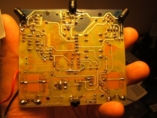
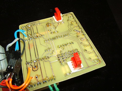
The body is now basically finished. I went to work on the electronics. For this robot I decided to use the PNA4602 modulated IR detector. The reasons for this were: It was cheaper, easy to obtain and didn't take up much board real estate. The PNA4602 detects 38kHz modulated IR which I would generate through the microcontroller. I took the exsisting board design from Blaster shark and modified it to put the sensors on the board and shrink the overall sized of the PCB.
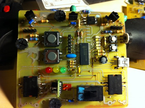
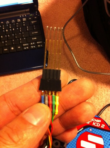
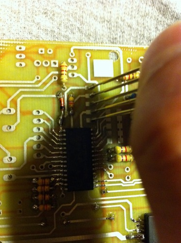
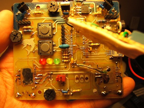
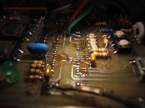
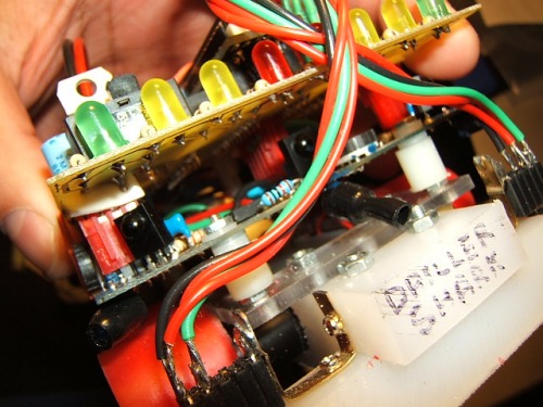
Here is the board populated. Its a thing of beauty. For this board I decided to do somthing a little different. Instead of putting a header on it for programming the bootloader onto the PIC, I instead put landing pads connected to the programming pins. I then made a jig to connect the programmer to the landing pads. I got the pogo pins from Solarbotics if you are interested.
I then painted the board next to the IR leds to reduce any leakage that would set off the sensors. This added with some heat shrink helped reduce the false readings.
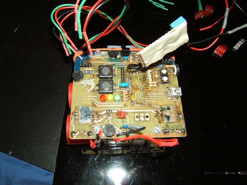
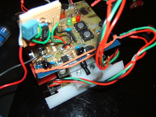
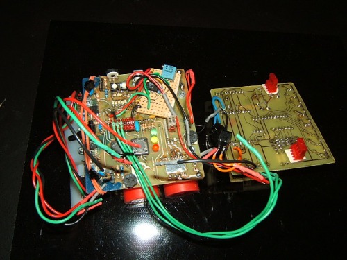
Time to put this puppy together.
Robot for the win!!! Or so I though. I was having problems modulating the IR LEDs with the microcontroller. For the life of me the micro just didn't want to switch fast enough, so I cranked out a 555 timer and spliced it into the circuit and everything worked.
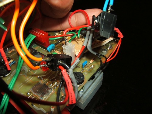
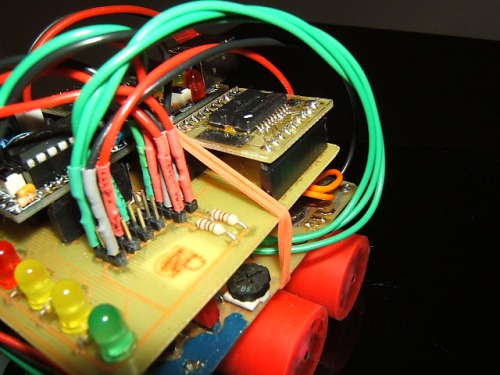
So at this point everything was working fine. Then I noticed that the motors on the right side out just mysteriously cut out. I was able to determine that the motor drivers were locking up cause of a large voltage spike on the outputs. This would make sense since I was running two motors off one driver. However when debugging the problem I fried the board :(. With one day before the competition I was in a bind.
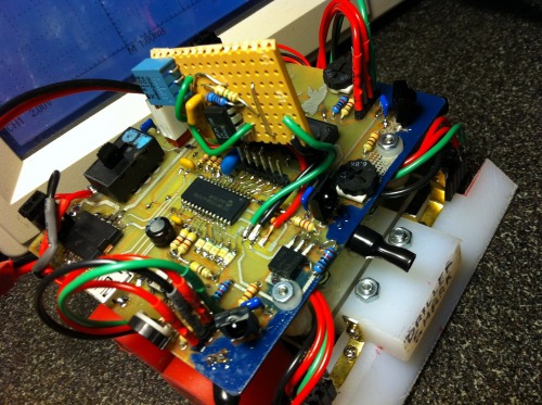
I fortunately had an extra control board which I grafted on and was good to go. Some of you may recognize the new board from my other sumobot Samm. It was the extra one I built for the new revision. I'm so glad I did :D.
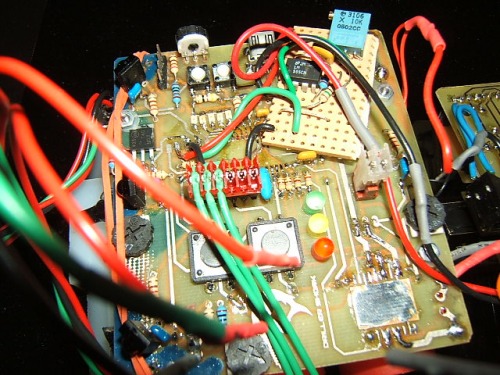
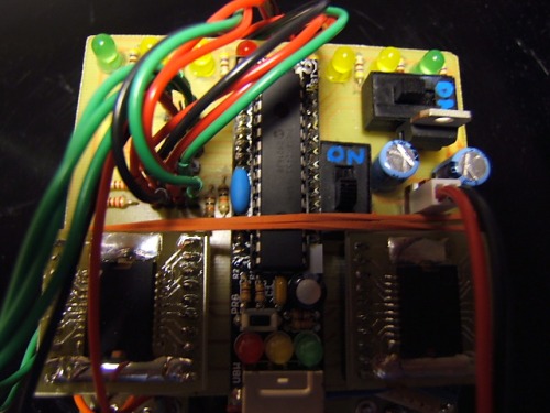
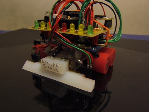
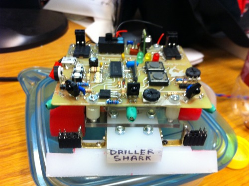
And here it is in all its glory. It still exhibited the same behavior with the motors as the other board, but I didn't really care at that point. It was working and I would leave for Toronto in a couple of hours. It did ok during the competition. I will try to get the videos up soon. Some problems that I noticed with this robot are:
Speed - It was slightly slower than I would have liked.
Weight - I should have made it heavier to gain traction to make up for its slowness
Staggered wheels - when I was caught up on something There would be no wheels on the ground.
That is all for now. I have decided to overhaul this robot, I will reuse the base and figure out a better way to control the motors.
- Actuators / output devices: Maxon Motors
- Control method: autonomous
- CPU: Microchip PIC 18F2455
- Power source: 11.1V 360mAh lipoly
- Programming language: C
- Sensors / input devices: panasonic PNA4602
- Target environment: on a dohyo(sumo ring)