


'Tachycardio' is a larger-scale, higher fidelity iteration of a previous biometric robot project 'Two products of a heartbeat'. The handmade chassis of 'Two Products' limited its walking ability. With biometric capabilities out of the way, 'Tachycardio' is an exercise in the articulation of a robot.
Purpose
Tachycardio is being developed for a show by Elektrolab in Brisbane due to be completed sometime before September. The show is conceptualised as an ecclectic arcade, Tachycardio being placed among other interactive art pieces.
Concept
Users race their crawling, wiggling pupa-larva-robot with their heart rates across a surface. There is a random chance that a large, crab-like robot controlled by all the player's heart beats emerges mid-game sweeping the racing surface. The game temporarily switches to a cooperative mode as the players have to attempt to align their heart beats.
The concept is very similar to my previous project in that the goal is to ask the audience to identify with their heart beat as a life giving process they have little direct control over, and subsequently highlighting our dependence on the biological and the subconscious. In Tachycardio, asking the user to attempt to control their heart rate, accelerating it potentially to an uncomfortable extent, makes them super aware of their heart and its limitations, perhaps at the cost of emphasis on the subconscious.
I'm hoping a competitive/cooperative premise will engage the audience more. The power of visualising biometrics is demonstrated throughout interactive art.
Sean Montgomery uses interactive biometrics frequently in projects such as Hivemind (that explores subconscious communication of brainwaves between individuals) and Emergence (which creates a visual link between electronics and the biological body).
The power of organic machines in a fine art setting is demonstrated in the portfolio of Michael Candy, who anthropomorphises and mystifies robots. See: Little sunfish, Cryptid, Azimuth.
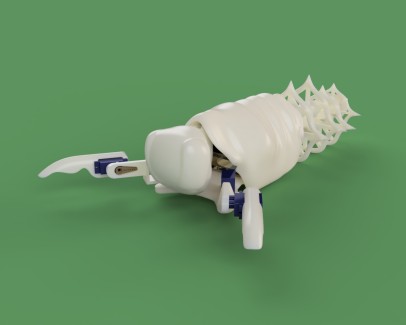
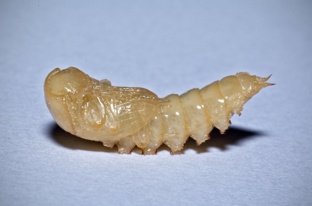
Aesthetic
The robot combines some features of sea fleas / mole crabs and a darkling beetle pupa which I've handled lots through my mealworm farming adventures. The tail will be covered in sand-coloured suede and the eyes will glow bright white.

Technical
The gait of the robot is inspired by Slant Concepts' Crawling Robot,
After investigating a dozen modes of robot locomotion, I chose this gait because it is simple and stable while still being dynamic and organic. Other gaits rely on a considered centre of mass or were not sufficiently dynamic.
The arms of the Pupabot are inspired by hexapod designs, but specifically I looked to Jason Leung's Quadraped Robot.
The print-in-place tail is inspired by the many flexi-toy designs on Thingiverse.com, such as this lizard.
Cad
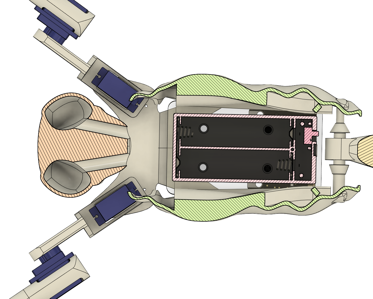
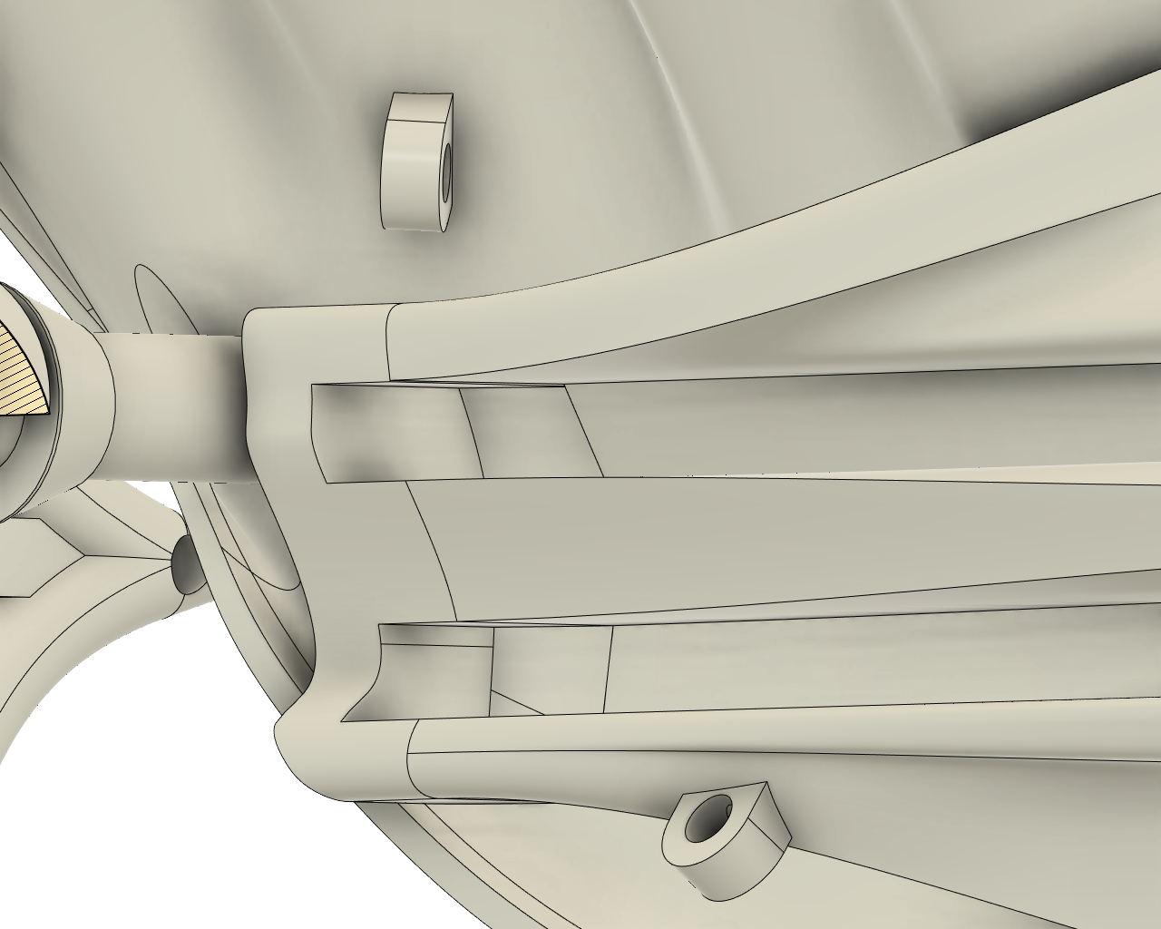
The shell houses two acrylic plates supporting the power supply and Microbit. The plates sit on rails and are stopped at the end. I suspect after prototyping I might have to pitch the tails down toward the stoppers, but the shell might also be in a tilted position due to the gait anyway,
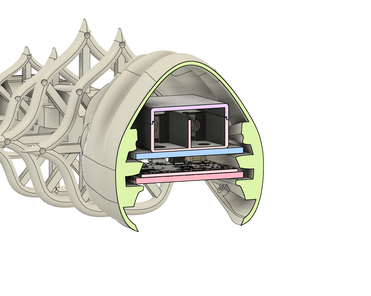
Another view of the shell cavity.
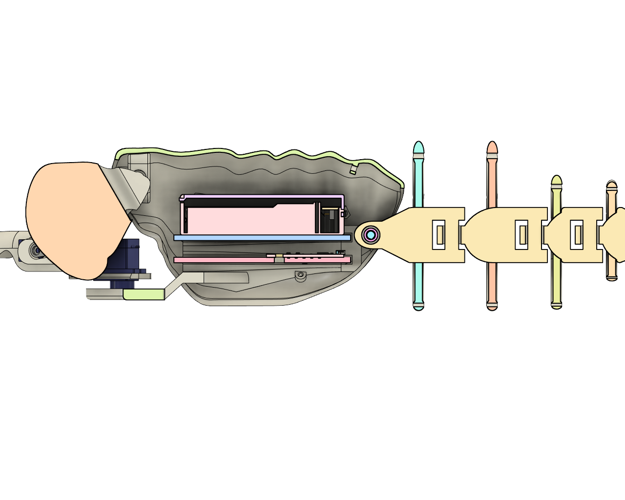
7.5mm tunnels for 5mm LEDS to be inserted into the eyes from the inside. The eyes are a thin-walled cavity so that they pass through but diffuse light while the head is solid (depending on infill).
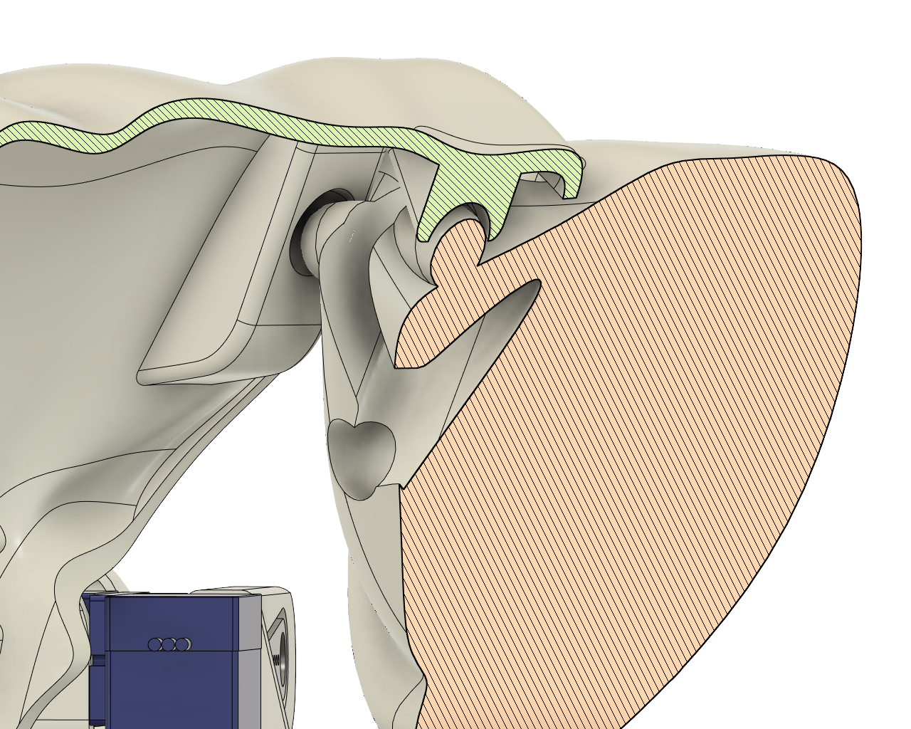
The head is held in place by (hopefully) flexible prongs that compress with a pinch.
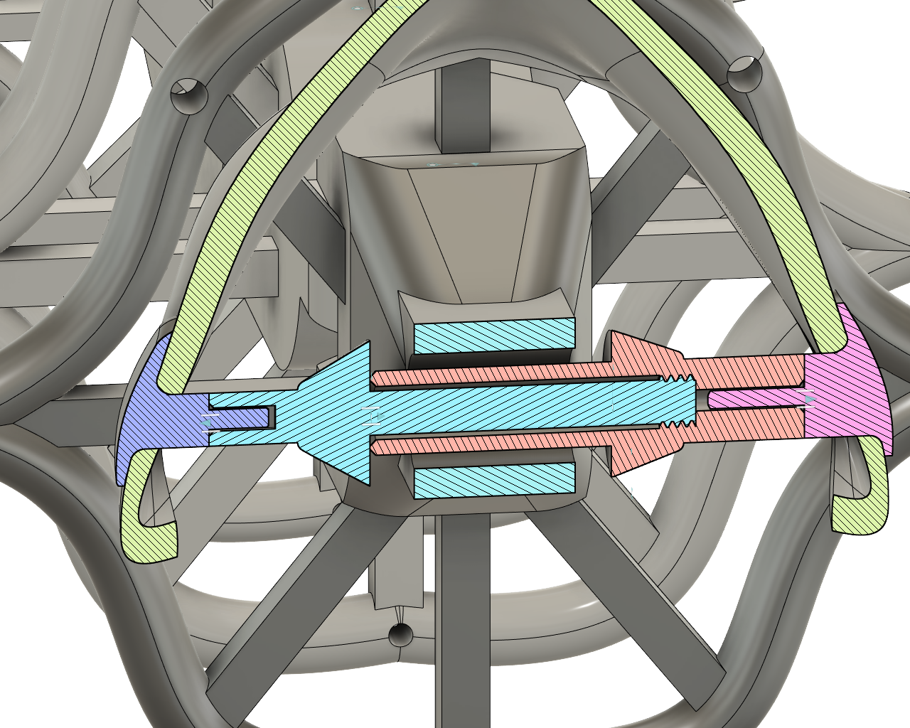
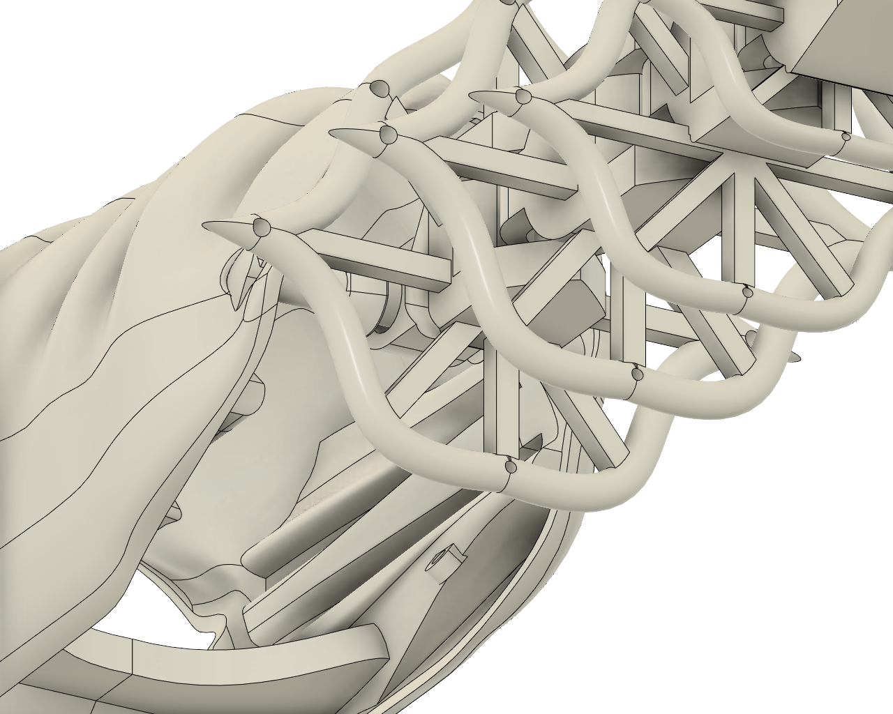
The Print-in-place tail chain is attached to the shell via a separately printed axel. It took extra time to figure this one out and I am not entirely sure that it will work. I will have to find out through physical prototyping.
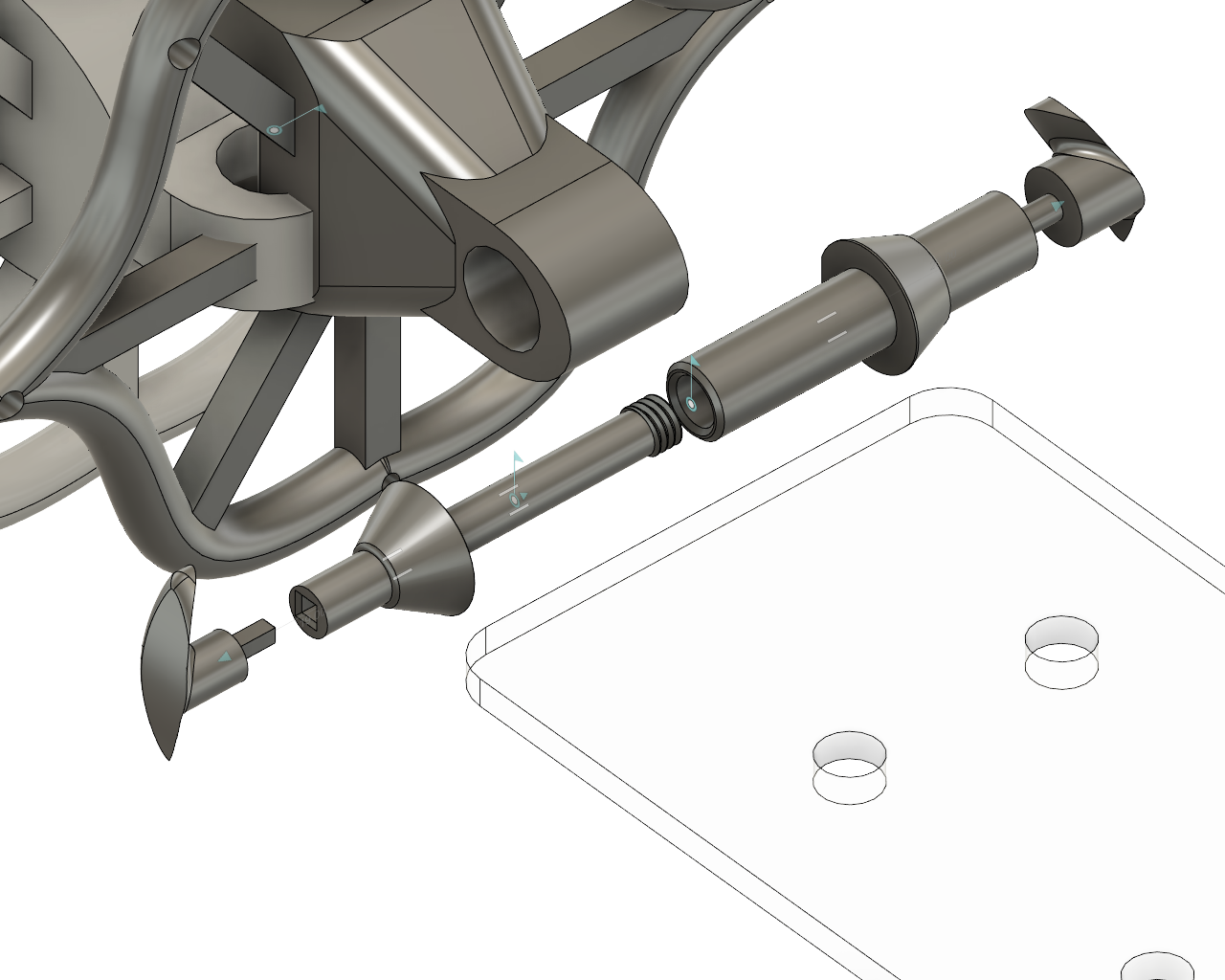
First the inside components of the axil are inserted into the hole of the tail chain. Then caps are inserted into the inside components of the axil through the outside.
Comes Apart Like this:
A suede cone is attached to the body via thread holes in post-printing. There are 6 on each frame, and 6 on the inside of the shell.
The print in place tail and the frames are separated in the printing files to print more efficiently.

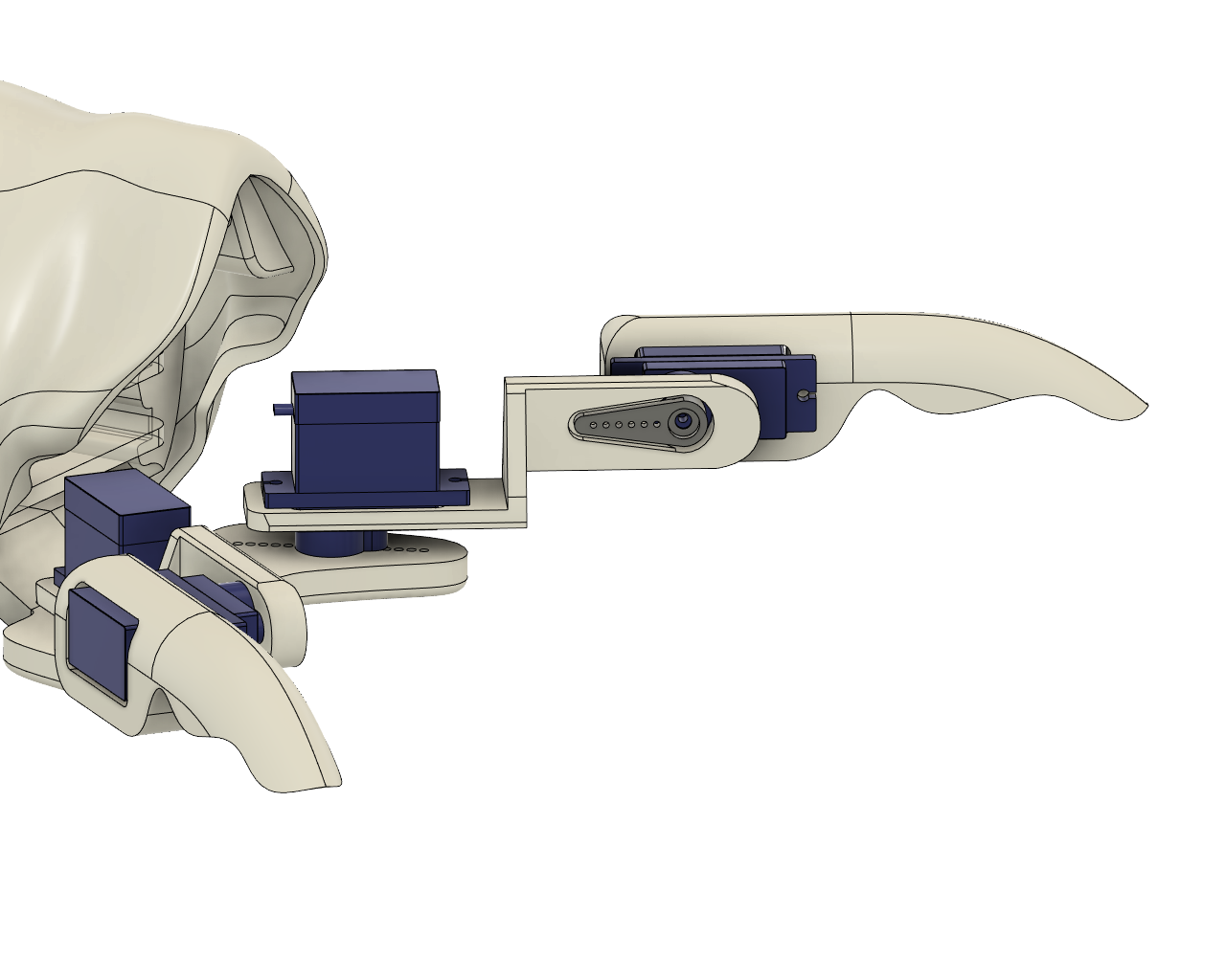
Servo arms accommodate 4 generic 9g servo and are screwed on.
A video demonstrating how these parts come together
Imported Model Credits
Intentions
Final will require 2-4 racing robots, and one big crab robot. The racing surface will be gritty to aid traversal. Ii will be elevated about a meter from the ground, about a meter wide and 1.5m long. It will be surrounded by painted timber walls with a wide lip, which the robots are pulled back into via string at the end of each round. There is a finish line to signify a win state. Pulse sensors in decorative casings are lined up on the lip of one of the walls. The casing also controls how the player contacts the sensor, to insure even and honest contact (the system can be cheated by moving the finger a whole lot).
I'd love to work a blue light/blacklight into it to make the robots glow much like scorpions. The arcade 'machine' case will be of a fluro pink and green colour palette.
Both STL files are sized for an Ultimaker 2+
pupabot_seperated_part1.stl is large, I will try to print it with 2mm layer height, 15% infill and 65% overhang tree supports. All other settings are default Cura settings.
pupabot_seperated_part1.stl is smaller, 1mm layer height, 20% infill and 50% overhang tree supports. All other settings default.
pupabot_assembled.stl is simply for illustrative purposes and should not be printed.
As I haven't yet printed the model, a demonstration of how it comes apart and is put together is above. When I print it and finalise the model I will also attach photos.
- The tail frames and the tail chain are printed separately to make printing more efficient. Slide the frames onto the chain and glue them on. Integrity is not super important for the tail.
- Fitting the axel in the tail is a 2-step process: first fit one half of the axel through the end vertebrae, screw the other half of the axel on. Then line up the fitted axel and end vert with the inside of the holes in the chassis. Slide the axel caps into the chassis holes from the outside, into the axel. The larger axel half fits the cylindrical cap and the smaller axel half fits the prism cap.
- Fit a suede cone over the tail and attach the fabric to the frames by threading a needle through the holes along the perimeter of the tail
- Tie the ends of the suede cone to the loops on the inside of the shell.
- Insert LEDs and wire into the eye holes in the back of the head piece.
- The acrylic plates supporting the battery and the microbit (and all of the connections) should be inserted before connecting the head.
- The head needs a bit of a squeeze to take out/put in. The flatter surface is 'Up' so it is printed upside down.
- The legs are held together by servos. The second joint should be assembled first, fitting the claw behind the servo body screws. The servo should be facing the inside of the body. Fit the forearm piece over the servo head with the side that has a gap for the shorter servo arm. Fit servo arm over it and screw it on. Once again it should be facing the centre-line of the body.
- Fit the second servo into the other side of the forearm piece. The screws should be facing upwards. The arm piece should be fitted behind the servo. Then fit the second servo head through the hole in the shell, screwing a double servo arm on the other side once again.
- Repeat 8 - 9 on other side.