


Sun Chaser
Not much to say about it at this point; this little guy is basically going to be a living ornament.
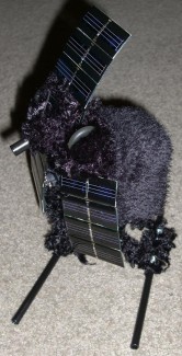
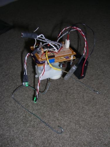
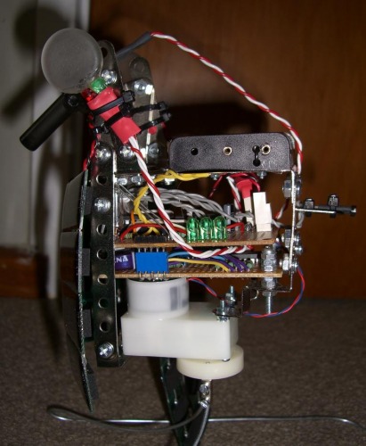
He's looking pretty ugly at the moment but once I've finalised the power systems I plan on building a wire frame to cover everything above the legs, and then I'll wrap the frame in fuzzy black fabric. The obscure glass tube dangling around on the right of the main photo is going to be the 'beak', which lights up when the bot chirps using the piezo speaker. The two pairs of LEDs flopping around on the front will be epoxied to two flat glass disks to act as eyes, which light up green or red depending on remaining power and other status conditions.
The main behaviour routine is basically as follows:
• Wake up - when power is restored he chirps a little 'waking' tune and flashes his eyes green.
• He checks to see if the light is stronger in front or behind him using the front/back LDR couple; if behind he spins around until the light source is in front.
• Once the light source is in front, he attempts to lock onto the light by turning CW or CCW based on the readings from the front-left/front-right LDR couple.
• To reduce the amount of flailing around there's a certain laziness factor which causes the bot to fire the motors less often if he's repeatedly changing direction, which happens when he's pointing almost directly at the strongest light source.Bot is now set to ultra-lazy in order to save on power.
• Every now and again, using erratic readings from the EMF sensor as a 'seed', he'll emit little chirping noises.
Other behaviours are:
• Once aiming approximately at the strongest light source, the bot checks to see if the light level is above a preset intensity - if it is not then the bot makes an "I'm going to sleep" chirp and shuts off all peripherals to save power. The bot will wake up again should the light level increase or if the lighting conditions change so that the light is stronger behind him.
• The bot continuously checks a mercury tilt sensor that trips when he is tilted more than 90° in any direction from the vertical axis. If he falls over, he makes a sad little chirp and then basically goes to sleep until he's put the right way up again. This stops him wasting power and potentially getting himself into an even worse situation by thrashing around.
• As well as controlling the eye LEDs, the internal voltage sensors check to see if the supply voltage exceeds preset values: currently one is set to 3.0V and the other is set to 3.7V. If the supply falls below 3.7V, the bot will become more lethargic in its activity, and if the supply falls below 3.0V the bot puts himself into low power mode by disabling the motors and shutting off some of the LEDs.
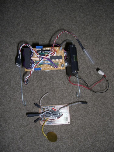
Here you can see the two PCBs seperated.
The lower board (top of frame) contains the EDL supercapacitors, a ULN2803A and 2 BC327 PNP BJTs. The supercaps provide backup power to cover for short periods when available sunlight is obstructed. The ULN2803A is an 8 channel 500mA Darlington Pair array, which I use to control the LEDs. 2 of the Darlington Pairs are used as the low-side transistors in an H-bridge that drive the motor, while the BC327s act as the high-side of the bridge. There's also a pair of normal caps for motor smoothing.
The upper board (bottom of frame) contains the PIC16LF628A μcontroller, the piezo disc, the mercury tilt sensor, the EMF antenna, 2 pairs of LDRs (one front/back, the other front-left/front-right), the low light LDR sensor, the voltage reference sensors (those two small red LEDs are actually part of the voltage reference), and finally a 74HC04 non-Schmitt inverter IC. The 628A handles all the control, but as a smaller baseline μc it doesn't have a 'true' ADC module, so I use the 74HC04 to clean up the signals from the LDR sensors and the voltage references. If I connected the sensors directly to the 628A inputs then there would be no clean transition at the trigger point thanks to 'forbidden zone' hysteresis between Vih and Vil (high and low input trigger levels). The 74HC04 changes output state at almost exactly Vsupply/2, which makes it very useful for testing changes in the light balance of the LDRs, and for getting a yes/no reading from the analog voltage references.
I'm making this bot for one of my sisters as part of a birthday present, so looking/acting cute and not requiring much maintenance are essential. Fortunately he's programmed using ICSP (In Circuit Serial Programming), so I can modify the software very quickly by plugging him into my PICKit2 USB programmer.
Edit 20/8/09: Fixed up the supply voltage sensors, both are working now. As usual I've tweaked the code again slightly, I'm uploading a code of the latest version.
Edit 4/9/09: Hmm, lots of other things getting in the way recently, most noticeably a large computer vision programming project. Back in the game now though, code has been significantly updated again. Solar Panel arrays are all fabricated, so I'm looking to start on the final assembly.
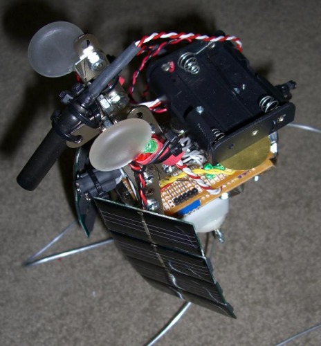
Edit 20/9/09: Finally got this little guy finished! Quite pleased with how the whole thing turned out. I've added a video of him in action, and I'll add a few more photos below:
Act cute, try to keep itself charged
- Actuators / output devices: piezo speaker, 1 x GM17 HE Gearmotor, several comm. LEDs
- Control method: Full autonomous
- CPU: PIC16LF628A
- Power source: Photovoltaic array, 2 x 1F supercapacitors, 3 x AA (NiMH or alkaline) optional battery pack
- Programming language: Assembly
- Sensors / input devices: Tilt sensor, 2 x LDR couples, 1 x LDR single, 2 x supply voltage sensors, EMF antenna
- Target environment: Window sills, desktops