


Start Here Robot (SHR) using the Actobotics Runt Rover Peewee chassis
There are many ways to build a robot, from scratch a kit, a prebuilt system or combination of any of these methods. The path we will take here will be mostly from a kit and other items such as an Arduino controller, motor driver and sensors from eBay or other vendors.
The chassis kit I use for this project is the Peewee which comes from Actobotics, from their Runt rover line but any two wheeled small robot kit will work fine as well for this project.
I chose the Peewee because it's small, inexpensive, durable, has lots of mounting options and is easy to put together. To assemble it you need no tools and can follow the video supplied by the manufacture. It can be assembled in under 10 minutes or less by most persons.
Step one: obtain all the parts and software.
Parts you will need are as follows:
- Runt Rover Peewee chassis or a suitable replacement
- Arduino Uno or similar board with USB cable
- Arduino Motor shield R3 or clone
- SG90 mini servo
- HC-SR04 or similar ultra sonic sensor
- Female to Female jumper wires
- Double sided sticky tape
- Small plastic soda bottle top
- A hot glue gun or rubber cement
- A 'AA' 4 slot battery holder (for alkaline) or a 5 slot (for rechargeable's) or one lithium ion 2 cell pack (7.4v) and charger (I highly recommend a li-ion pack to power most small bots) See more information on batteries below.
Things you will need to download:
- The Arduino IDE
- The Motor shield library from Github
- The Robot code below or the attached .zip
After you have purchased, collected and downloaded everything thing you're ready to start with the build!!!
Assembly:
First assemble chassis following the instructions included with the chassis or video. After finishing you should have something like this:

Next attach the Arduino controller board and motor shield together then place them into the clip holder or onto your screw mounts (if you are using another type chassis). After you're done with that it should look something like this:

Now you can start hooking up wire connections. First connect the motor wires to the motor output terminals on the motor shield. For this bot the left side motor (with the rear of the bot facing you) will be connected to the ‘A’ channel. The black wire is in the first terminal and the red the second terminal. This leaves the right motor going to channel ‘B’, with with black again on the first terminal and red in the second.

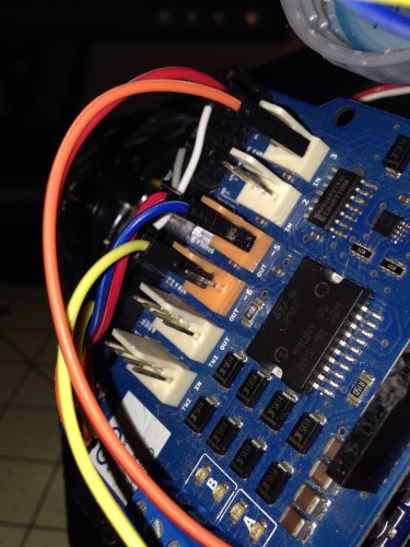
Next connect the HC-SR04 up by connecting VCC to one of the left pins of the tinker connector on the motor shield. The 5v (VCC) pins are the pins closest to the black female pin rail for the Arduino pins 0-SCL. After this is done, connect the GND pin of the sensor to the right pin of the tinker connector. After that, connect the Echo line to the Arduino’s pin 2. You can either connect it to the middle pin (the pin between VCC and GND) on the tinker connector for pin 2 or on the black rail for pin 2. Now connect the Trigger line to the Arduino’s pin 5. Again you can choose to either connect it to the middle pin (the pin between VCC and GND) on the tinker connector for pin 5 or on the black rail for pin 5.
 5
5
(Servo and Sensor connected up on the motor sheild tinker connectors)
Now you can hook up the servo. Connect the GND wire (usually black or brown, but opposite side of the white or orange wire. Place it on one of the tinker connector gnd pins. Then connect the servos center wire to a tinker connectors VCC. Finally signal wire (white or orange) to the center pin for the tinker connector for pin 6.
To place the servo on the bot, cut a small piece of double sided sticky tape and stick on the bottom of the SG90 servo. Take the servo and place it in the center of the two holes at the front of the chassis. NOTE: If you have two screws that fit the servo and chassis holes that are long enough, you can use those :-) Take the plastic soda bottle top and carfully cut a slit across it (see picture below), wide enough for the sensor board to slide into. Use a little hot glue or rubber cement on both sides to hold it in place. Now take the servo cross attachment horn “+” and glue it to the top side of the bottle cap. You can also drill a small hole with a small drill bit or even a little screw driver into the center of the top to help secure the mount even better on the servo with a screw.

(Top with slot cut into it and one with the sensor mounted and glued in)

(Hole drilled for servo horn and screw)

(Cross '+' servo horn glued to bottle cap)
Once you have the sensor ready to mount on the servo, place it on the horn and turn the servo slowly and VERY gently all the way in one direction, then the other to figure out the middle point. Once you think you have it, press the sensor on without the screw until you are sure it's in the correct position.
Now... Recheck all the wiring!
- Left Motor Black wire --> Motor sheild 'A' first teminal
- Left Motor Red wire --> Motor sheild 'A' second teminal
- Right Motor Black wire --> Motor sheild 'B' first teminal
- Right Motor Red wire --> Motor sheild 'B' second teminal
- HC-SR04 VCC --> Motor sheild tinker connector pin for VCC (pin closest to the Arduino pin rail)
- HC-SR04 GND --> Motor sheild tinker connector pin for GND (pin furtherest away from the Arduino pin rail)
- HC-SR04 ECHO --> Arduino’s pin 2 (either on middel pin of the tinker connector for pin 2 or the Arduino’s pin 2 on the rail)
- HC-SR04 TRIG --> Arduino’s pin 5 (either on middel pin of the tinker connector for pin 5 or the Arduino’s pin 5 on the rail)
- Servo GND (Black or Brown) --> Motor sheild tinker connector GND pin
- Servo VCC (Red) (servo center wire) --> Motor sheild tinker connector VCC pin
- Servo signal wire (white or orange) --> Motor sheild center pin for the tinker connector for pin 6.
With the wiring checked and rechecked, It's time to load the code.
Follow the intructions on the Arduino site on how to install the Arduino IDE. After the IDE is installed, you can next install the Motor Driver library. Do this by down loading the zip file and extracting it to your Arduino libraries folder or by following these instructions on how to add a libary. Once the libary has been loaded, copy the below program and past it into the Ardriono IDE. Connect your PC and Arduino up with the USB cable. Now choose the board from the Tools->Board menu in the IDE, Uno for this project (choose the board you have if different from Uno) Now from Tools->Port menu, pick your com port. After this is done, click the upload button. If all went well, the code was loaded, if not see here for help on the IDE and related issues.
After the code has been loaded on to the controller, you can hook the battery pack up. If you are using a battery holder (with no batteries at this point), hook the black wire to the motor shield motor power in GND and the red to VIN. If you have a li-po or li-ion, you can use jumper wires as pictured to connect the battery, again black to GND and red to VIN.

(VIN and GND on the Motor sheild)
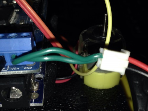
(LI-ION battery connected to VIN and GND by two small 22gauge wire pieces)
As you make the last connection, you may want to hold the bot in one hand whilst doing it or it may get away from you! I do have a 30 second delay at startup to give you some time for adjustments. Once the bot powers on, the sensor servo is set to the neutral position (angle 90) and then the 30 second delay begins. At this point if you need to reposition the sensor mount, you can do so. After the delay has completed, the bot will move forward if all the connections were right and made well. If not, recheck them again and make any corrections needed. If they are right and the sensor looks centered enough, you can screw the bottle top to the servo using one of the servo screws that came with the servo. If the robot is moving backwards or turning instead of going forward at first move, switch the motor wires on the sheild terminals until they are correct (you may have to play around with it some)
Your bot and batteries.
One of the most common mistakes and problems for beginning robot builders is battery choice. Most pick batteries they are familiar with like 1.5V ‘AA’ or 9V alkaline or “Super duty” batteries. These are cheap and easy to get. However are not the correct choice though for powering your bot!!! A robot has a computer, motors, motor drivers and sensors that all need power. ‘AA’, 9v alkaline or the like will NOT supply enough power for them all.
In this day and age you have a lot of different battery types to choose from; NiCAD NiMH, Li-ion and Li-po just to name a few. They come in many shapes and voltage/mah sizes. For this robot or most any beginner bot I highly recommend using Li-ion 7.4v packs. They are relatively inexpensive for the power they give and easy to work with. For a good 7.4v pack you will expect to pay at least 10$USD. You will also need a charger, and one can be had for near the same pice as the batteries.
Now you could go with NiCAD or NiMH 1.2v ‘AA’ size rechargeable, and you will need at least 5 of them to get the same voltage as 4 normal ‘AA’s. This is not a big issue since you can get 5 slot ‘AA’ holders. Rechargeable’s are easily found at most department, sporting or electronic stores. Buying 5 batteries and a charger may be around the same cost as the Li-ion option.
You can find both batteries and chargers on eBay, Adafruit, ServoCity, Sparkfun or hobby sites like HobbyKing and many other places. Do shop around!
Final battery note... Picking a battery for your bot may seem trivial, but it will weigh a lot more in it's performance than any thing else at first!!
The video above shows the bot in action. The code running on the video bot has close object reaction distances (2cm) and driving faster to show the maneuverability of the bot. It just wants to run free like other little robots!
The Code for the bot:
/*
   Basic Arduino obstacle avoider.

   Goal in life...
      Moves forward looking for obstacles to avoid :-)

   Use to get started for a SHR (Start here robot) (https://www.robotshop.com/letsmakerobots/)

   Written by Scott Beasley - 2015
   Free to use or modify. Enjoy.
*/

/*
   Uses the MotorShield library. It works with the Arduino Motor shield R3.

   Download from https://github.com/jscottb/MotorShield or clone the zip from
   https://github.com/jscottb/MotorShield/archive/master.zip
   Unzip and copy to your Arduino library folder or follow the instructions
   here: http://arduino.cc/en/guide/libraries

   Note: You may need to remove the '-master' from the archive file name to add
   the library
*/

// Using the Arduino Motor shield R3 (http://arduino.cc/en/Main/ArduinoMotorShieldR3)
#include <MotorShield.h>
#include <Servo.h>

// Defines for the distance reading function of the bot.
#define turn() (left_dist >= right_dist) ? go_left () : go_right ()
#define microsecondsToCentimeters(microseconds) (unsigned long)microseconds / 29.1 / 2.0
#define MIN_ACTION_DIST 5 // 5 cm
// Change these defines if you use differnt pins
#define ECHO_PIN 2  // Digital pin 2.
#define TRIGGER_PIN 5 // Digital pin 5

// Speed defines
#define MAXFORWARDSPEED 190 // Max speed we want moving forward
#define MAXBACKWARDSPEED 130 // Max reverse speed

// Various time delays used for driving and servo
#define TURNDELAY 450
#define BACKUPDELAY 300
#define SERVOMOVEDELAY 200
#define SERVOSEARCHDELAY 85

/*
   Globals area. Try to keep them to a minimum :-)
*/

// Create the motor and servo objects with use to interface with
MS_DCMotor motor_left (MOTOR_A); // Create Left motor object
MS_DCMotor motor_right (MOTOR_B); // Create Right motor object
Servo sensor_servo; // Create a servo object for our distance sensor

byte sweep_pos = 0; // Current position of the sensor servo
byte pos_index = 90;
unsigned long left_dist, right_dist; // Distance measured left and right

void setup ( )
{
   Serial.begin (9600); // Set Serial monitor at 9600 baud
   Serial.println ("My SHR bot is starting up!");

   // Make sure the motors are off at start
   halt ( );

   sensor_servo.attach (6); // Attach the servo to digital pin 6
   sensor_servo.write (90); // Set the servo to the middle (neutral) pos

   // Set modes for distance sensor pins
   pinMode (ECHO_PIN, INPUT);  // Set echo pin as input
   pinMode (TRIGGER_PIN, OUTPUT); // Set trigger pin as output

   // Delay to give user time to make adjustments.  Remove after done.
   delay (30000);
}

void loop ( )
{
   unsigned long dist_fwd;

   // Rotate the distance sensor as we drive along
   rotate_sensor ( );

   // Give the servo time to get to position and get setted
   delay (SERVOSEARCHDELAY);

   // Get a reading from the current sensor direction
   dist_fwd = ping ( );
   Serial.print ("Distance sensor reading: ");
   Serial.println (dist_fwd);

   // Go forward while nothing is in the distance sensors read area
   if (dist_fwd > MIN_ACTION_DIST || dist_fwd == 0)
   {
      go_forward ( );
   }
   else // There is something in the sensors read area
   {
      halt ( ); // Stop!
      go_backward ( ); // Back up a bit
      delay (BACKUPDELAY);
      halt ( ); // Stop!

      sensor_read ( ); // Read distance left and right

      turn ( ); // Turn toward the clearest path
      delay (TURNDELAY);
      halt ( );
   }
}

// Read the sensor after we find something in the way. This helps find a new
// path
void sensor_read ( )
{
   Serial.println ("Server at 40 deg...");
   sensor_servo.write (40);
   delay (SERVOMOVEDELAY);
   right_dist = ping ( ); //Look to the right

   Serial.println ("Servo at 140 deg...");
   sensor_servo.write (140);
   delay (SERVOMOVEDELAY);
   left_dist = ping ( ); // Look to the left

   // Set the servo back to the center pos
   Serial.println ("Servo at 90 deg...");
   sensor_servo.write (90);
}

// Rotate the sensor servo at 45deg increments
void rotate_sensor ( )
{
   if (sweep_pos <= 0) {
      pos_index = 45;
   }
   else if (sweep_pos >= 180) {
      pos_index = -45;
   }

   Serial.print ("pos_index = ");
   Serial.println (pos_index);
   sweep_pos += pos_index;
   Serial.print ("sweep_pos = ");
   Serial.println (sweep_pos);
   sensor_servo.write (sweep_pos);
}

// Read the HC-SR04 uSonic sensor
unsigned long ping ( )
{
   // Trigger the uSonic sensor (HC-SR04) to send out a ping
   digitalWrite (TRIGGER_PIN, LOW);
   delayMicroseconds (5);
   digitalWrite (TRIGGER_PIN, HIGH);
   delayMicroseconds (10);
   digitalWrite (TRIGGER_PIN, LOW);

   // Measure how long the ping took and convert to cm's
   return (microsecondsToCentimeters (pulseIn (ECHO_PIN, HIGH)));
}

void go_forward ( )
{
   Serial.println ("Going forward...");
   motor_left.setSpeed (MAXFORWARDSPEED);
   motor_right.setSpeed (MAXFORWARDSPEED);
   motor_left.run (FORWARD|RELEASE);
   motor_right.run (BACKWARD|RELEASE);
}

void go_backward ( )
{
   Serial.println ("Going backward...");
   motor_left.setSpeed (MAXBACKWARDSPEED);
   motor_right.setSpeed (MAXBACKWARDSPEED);
   motor_left.run (BACKWARD|RELEASE);
   motor_right.run (FORWARD|RELEASE);
}

void go_left ( )
{
   Serial.println ("Going left...");
   motor_left.setSpeed (MAXFORWARDSPEED);
   motor_right.setSpeed (MAXFORWARDSPEED);
   motor_left.run (BACKWARD|RELEASE);
   motor_right.run (BACKWARD|RELEASE);
}

void go_right ( )
{
   Serial.println ("Going right...");
   motor_left.setSpeed (MAXFORWARDSPEED);
   motor_right.setSpeed (MAXFORWARDSPEED);
   motor_left.run (FORWARD|RELEASE);
   motor_right.run (FORWARD|RELEASE);
}

void halt ( )
{
   Serial.println ("Halt!");
   motor_left.setSpeed (0);
   motor_right.setSpeed (0);
   motor_left.run (BRAKE);
   motor_right.run (BRAKE);
}