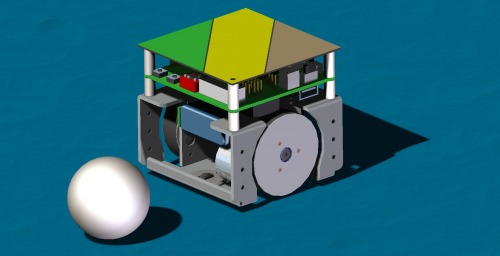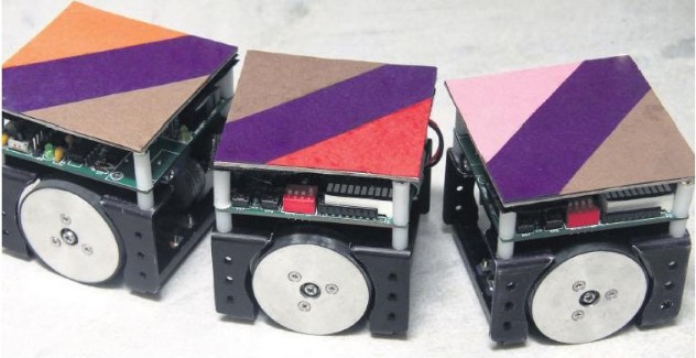
Squbot
Specification
Dimension : H = 70mm, L = 75 mm, W = 75 mm
Weight : 310 gm
Chassis : Aluminium, 2mm thickness, H = 42mm, L = 75 mm, W = 75 mm
Drive : Differential wheel drive with front & back free rollers
Microcontroller : PIC18F4550 capable to run on maximum 48MHz clock
Battery : 7.4V, 950mAH Li-ion battery
Motor : DC Motor RF-300FA (Torque up type), 6V, 3500rpm
Motor driver : L293D
Encoder : 24 ppr optical encoder, provision for quadrature encoder
Top Speed : 800 mm/s
Wheel diameter : 44.5mm including rubber tread
Ground clearance : 2.5mm
Communication : Wireless – Zigbee, Wired – USB & RS232
Sensor : Dedicated Provision for 6 A/D sensors, sensor daisy chain
Programmer : Supports USB & Serial bootloader or external programmer
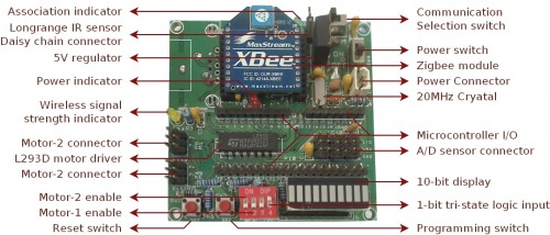
Detailed specification of main Controller Board
· PIC18F4550 8-bit RISC USB-microcontroller with 32 KB Flash Memory, 2KB SRAM
· Architecture optimized for C compiler supported by 8X8 hardware multiplier
· 10-bit 13-channel ADC, 2 PWM channels, 4 number of 16-bit timer etc.
· Lower EMI : External 20MHz & internal 48MHz clock using internal PLL multiplier
· On Board Regulated 5V Power supply for logic circuit
· Flexibility in programming via USB / Serial bootloader
· 10 bit logic display : 8-bit output from PORTD directly visible on bar-display
· Option for one bit tri-state digital logic input to microcontroller
· Separate microcontroller Reset switch
· Slot to insert XBee wireless communication Module
· All I/O pins of microcontroller is available for custom applications
· On board Max 232 Transceiver for asynchronous communication to PC
· Easy accessible Selector switch for wireless or wired communication
· Compact motor connector for feedback based DC motor control
· L293D motor driver for bidirectional speed control of two motors.
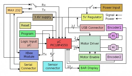
The Block Diagram of SquRobot
The mC pin connection table
Pin | Port Name | Dedicated connection |
1 | MCLR | Reset Switch |
2, 3 | RA0, RA1 |
|
4 | RA2 | 1 bit tri-state logic input |
5, 6, 7 | RA3, RA4, RA5 | Sensor connector |
8, 9, 10 | RE0, RE1, RE2 | Sensor connector / (RE0 Daisy chain drive) |
13, 14 | OSC1, OSC2 | Crystal Oscillator |
15 | RC0 | Bar Display |
16 | RC1/CCP2 | L293D (speed control PWM Motor-1) |
17 | RC2/CCP1 | L293D (Speed control PWM Motor-2) |
19, 20, 21, 22 | RD0, RD1, RD2, RD3 | Bar Display |
23, 24 | RC4/D-, RC5/D+ | USB Connector |
25, 26 | RC6/TX, RC7/RX | MAX232 |
27, 28, 29, 30 | RD4, RD5, RD6, RD7 | Bar Display |
33, 34 | RB0, RB1 | Motor-1 Connector (feedback) |
35, 36 | RB2, RB3 | Motor-2 Connector (feedback) |
37 | RB4 | S-PG switch |
38 | RB5 | Bar Display |
39 | RB6 | L293D (direction control Motor-2) |
40 | RB7 | L293D (direction control Motor-1) |
Communication module – Zigbee / RS232
SquRobot Provides two mode of communication to PC or to other robot: Wires - RS232 based or Wireless – Zigbee based. The selector switch as shown bellow makes user enable to select any on of the communication mode. ‘Z’ marking on the PCB indicates the Zigbee based wireless communication mode.
Zigbee module : XBee series1 or series2
Supply Voltage : 2.1 - 3.6 V
Operating Current (Transmit, max power) : 40mA (3.3 V, boost mode)
35mA (3.3 V, normal mode)
Operating Current (Receive)) : 40mA (3.3 V, boost mode)
38mA (3.3 V, normal mode)
Operating Frequency Band : ISM 2.4 GHz
Operating Temperature : -40 to 85º C (industrial)
Antenna Options : Integrated Whip / Chip
Supported Network Topologies : Point-to-point, Point-to-multipoint,
Peer-to-peer and Mesh (Series2)
Number of Channels : 16 Direct Sequence Channels
Design File - Rendered