SpurtBot, Shadow Runner
This post will document a new SpurtBot design. This design integrates a mini breadboard and can be set up as a no-solder project for kids by pre-soldering wires to the motor. I plan to make take advantage of the solderless breadboard to make several variations, which I will document on other robot pages.
Edit: I have posted detailed build instructions and a materials list over on Instructables. The video also provides a walk through of the build.
Behavior
The Shadow Runner will run from shadows. That is, it will drive forward in normal lighting conditions, but if you cover its light sensor with your hand or it runs into shadow, it will reverse and turn. In many cases, this will remove the robot from shadow and it will start to drive forward again. A disadvantage of this simple robot is that if it drives too far into shadow, it will just spin in circles on one wheel.
Circuit
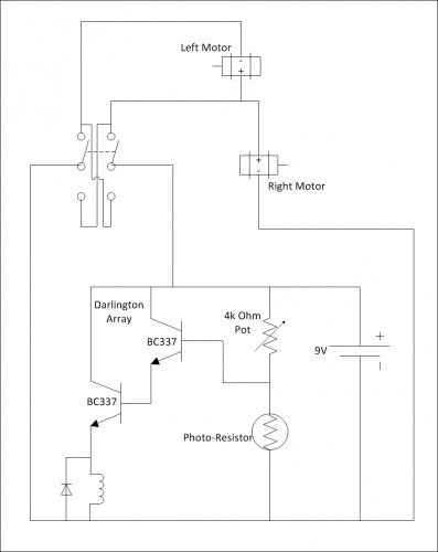
When the photo resistor sees light, the robot will drive forward. Both left and right motors are receiving 9V via the normally closed contact of the relay.
When the photo resistor is in shadow, its resistance increases dramatically, and the voltage divider formed with the potentiometer now increased the voltage at the input of the Darlington transistor array, turning it on. This activates the relay.
Now the left motor will get ground on its + lead, and 9V on its - lead, reversing the motor.
The right motor's - lead is hard wired to ground from the battery. Since the + lead of the right motor is now also getting ground, the right motor will stop.
This combination causes a stop, backup and turn maneuver. If this maneuver removes the shadow from the photo resistor, it will revert the relay to its normal position, and both motors will drive forward again. If the robot stays in shadow, it will spin in circles with the right motor stopped and the left in reverse.


