


SpurtBot - Light Follower
Introduction
SPURT is an acronym used by the University of Rostock in Germany. It stands for 'School Projects Using Robot Technology". I borrowed the concept for my first SpurtBot project. I had some guidance from LMR member Spurt, who I believe is associated with German team that developed the idea in the first place.
I created an addition design, the SpurtBot Shadow Runner, using a solderless breadboard. I had recieved feedback from teachers and other educators that a solderless (or at least, less soldering) kit would be better fit for younger builders.
The addition of a breadboard also makes it possible to come up with more than one circuit design, and to use them on the same chassis. I have been collaborating with Chris the Carpenter, and he designed the nice laser cut plexiglass chassis you see in this post.
Materials
- 2x motors Mabuchi FK-260A-10400 (Jamco p/n 2081908)
- 2x rolling bearings 608z
- 5/16in wood dowel (2 inches)
- 1x craft stick
- 1x punch balloon
- 1x 8mm half round bead
- 1x mini solderless breadboard
- 2x BC337 NPN transistor
- 2x photocell
- 2x 1.5V AA alkaline batteries
- 1x 2-AA battery holder
- 24in 22AWG stranded wire
- glue sticks
- 60/40 0.05” dia. solder
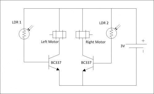
Refer to the schematic above while assebling the circuit.
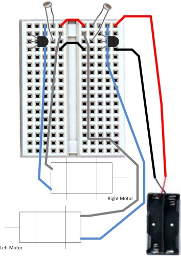

The picture above-left is a connection diagram. Refer to this diagram when following the instructions below.
Above-right is the assembled circuit. Note that in this picture, the wires may be different colors than described in the assembly instructions below. Also the two leads for the LDR on the right may look shorted, but there is actually a gap in height.
Light Follower assembly instructions:
- Flip the SpurtBot over so the breadboard is facing upwards.
- Remove all components and wires from the breadboard.
- Connect a jumper (shown in red on the figure above-left) between the two top rows of the breadboard. This is where the positive red wire from the battery will connect (not right now, though).
- Connect another jumper (shown in black on the figure above-left) between the two rows four down from the top of the breadboard. The contacts on the forth row down will be the ground connection for the circuit.
- Connect the black wire of the battery pack to the forth row down on the breadboard, the same row that you connected the black jumper.
- Leave the red wire from the battery pack disconnected for now. Later it will be connected to the upper-right row of contacts as shown.
- Connect the positive (blue) wire from each motor to the upper row of contacts, where the battery power will connect.
- Install two bc337 transistors as shown. The rounded “bellies” should face the right side of the SpurtBot. Each lead should be in a different row of the breadboard, starting with the collector (top contact) one row down from the top.
- Install two LDRs as shown in the upper-right and upper-left of the breadboard. One lead of each LDR should be in the same row as the middle “b” or “base” lead of the transistor. The other lead of eachLDR should be on the upper-right and upper-left of the breadboard.
- Connect the negative grey wire of the left motor to the “c” lead (the one at the top) of the RIGHT transistor. Look carefully. The leads of the left motor are on the right side of the SpurtBot, which is the same side as the transistor you are connecting to.
- Connect the negative grey wire of the right motor to the “c” lead (the one at the top) of the LEFT transistor. Look carefully. The leads of the right motor are on the left side of the SpurtBot, which is the same side as the transistor you are connecting to.
- Get your flashlight ready! Connect the “positive” red lead battery box to the upper-right row of pins. Turn the lights off. Your SpurtBot will move when you shine a flashlight on the LDRs. Can you position the LDRs so that you can control your SpurtBot to move left, right or forward?
Chases light in a dark room