


Speedy ATV
Hi guys!
Goggling around searching for information on arduinos and robots, I found this fantastic website. After spending hours reading your projects I decided to show you my current project.
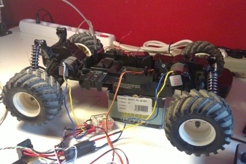
It was a RC car that my family gave me as a xmas present a long time ago.

My first idea is to make it autonomous with 2 srf02 modules and an arduino brain, but on the meantime I'm going to play with it changing the controller to digital using 2 xbee modules.
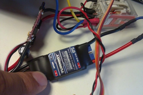
I didn't find much information about the motors but the old board was using two FET transistors 20A rated in parallel and two relays to control the forward/backward movement. I decided to buy two brushed ESC for the motors (one for each) but I think that just the rear wheels are going to be able to move backwards.
As this (cheap 5€ each) brushed ESC cannot switch rotation, I used the biggest relay I found in my electronic-stuff box. The problem, the relay is 24V.
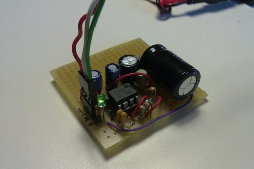
I make a stepup voltage converter based on a PIC programmer, the original converter gives 13,5VDC from 5VDC. I change something here and there and finally it gives me 28V from 7V of my battery. If someone is interested in the schematic just ask, the ic is a 555 for generating a clock signal.
This converter doesn't give much current but the big capacitor is responsible for the first push and then the battery gives the maintenance current.
As you can see in the photo of the ESCs, one is "naked". It is because this ESC sometimes works sometimes doesn't, I decided to open and resolder all joints (maybe a cold joint). Now it works ok.
And now the brain!
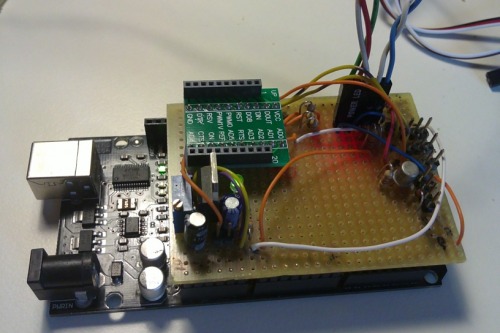
I am using an arduino mega board with a self made shield. So far the shield contains: 1) LM317 for the 3.3V regulator for the xbee 2) xbee adaptor 3) pins for the servo, front motor and rear motor 4) a transistor for the 24V relay.
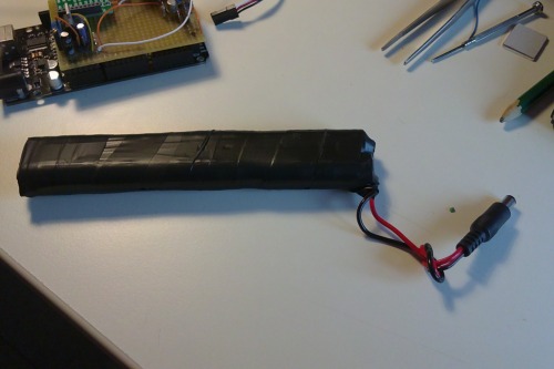
I also made a 6-nimh battery pack of 2200mah, not very satisfied with it but it's a start. I'm planning to buy some batteries with pads to solder and make a robust pack not this crappy one.
And finally the theorical speed. Always thanks to google I found this vehicle can reach a top speed of 38km/h, not bad for an oldie ( I believe it won't be easy fast and autonomous).
I will be updating soon with a video
Hope you like it!
drive fast
- Actuators / output devices: two motors, servo direction
- Control method: Xbee Wireless remote control
- CPU: Arduino Mega
- Power source: 7, 7.2V NiMH from 6 penlites (2 x 3)
- Programming language: Arduino
- Sensors / input devices: srf02, rear and front bumper
- Target environment: Indoor or outdoor