


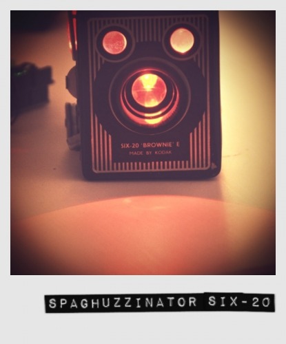
Spaghuzzinator SIX-20
The Spaghuzzinator is a classic end-world-scenario robot. Evil and lethal. Strong and without mercy. A true bad guy.
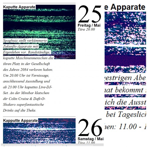
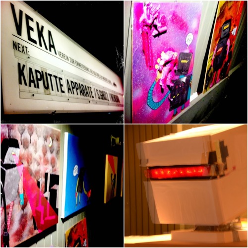
This robot is one part of an art exhibition project of a friend of mine (The man on this robot's profile picture). The exhibition Kaputte Apparate is about machine outlaws from the future 2084. Raise from trash these robots are not friendly.
This one wanders through a city and lasers everything down that moves. A terminator of its time.
Through the robot's eyes an evil speech is morsed and transmitted via speaker. This blinky talks.
Content
- The Robot's Head
- The Making-Of
- 15 Minutes of Fame
- Alternative Solutions
- Further Readings
The Robot's Head
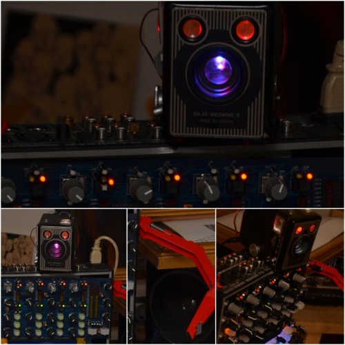
Since the friend is more artist and less engineer I suggested that I might support him with the robot's head - an old Kodak photo-camera. Instead of being still the head could get some skills and lights and a sound module so that the story the artist want to tell gets emphasized.
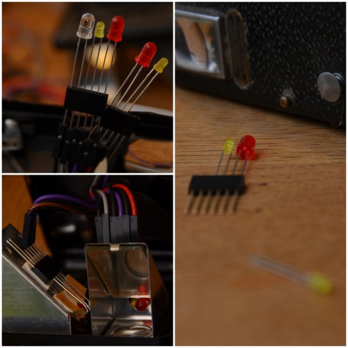
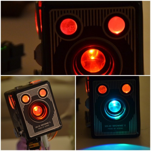
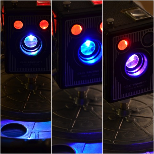
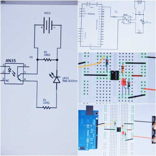
So I went on and implanted into this robot's head an Arduino Uno with some electronics and software. Extended the neck with a servo motor for smooth head rotation. Embedded some scary color LEDs into the robot's eyes. Embedded one self color changeing RGB LED into the mouth and mounted a 20-second sound module on one side.
Since the head is made from metal it is relatively heavy. This introduced some non functional requirements about the robustness of the mounting using one servo and some sort of mounting.
The Making-Of
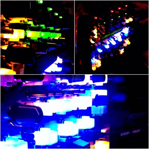
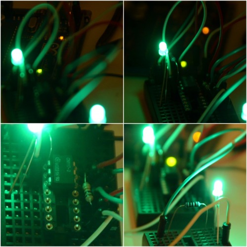
In one sweep all the LEDs where embedded and connected. To have some modifyability the LEDs are plugged into a female connector block.
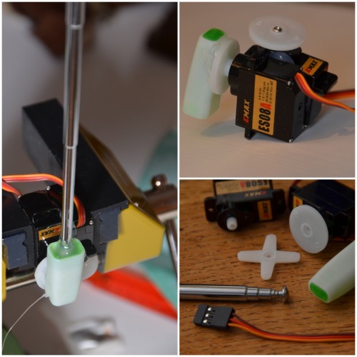
Then the mounting for two servos got developed. Two servos glued together and attached via a pen cup to an antenna. This solution is not rubust enough since the weight of the whole payload - in this case the head - sits directly on the servo gears. This makes a cheap servo look very bad under load. No move or sudden changes. Unuseable.
So I had to go on. But hey... start stupid and envolve. Another solution had to be found.
First smoke test of all LEDs. Looks cool.
And this is the body.
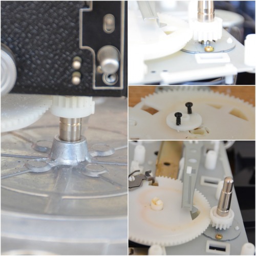
Still the head mounting is not solved so I brained on and found I should try the same sort of mounting the Fhotibot uses.
The gear of an old Pioneer vynil record player together with the silver vynil record mount could do the head mount job.
When running after a while this head started to behave oddly. The servo jumped and the LEDs went out. This odd behavior was reproducable by putting the servo under load. The more load I gave to the servo the faster the LEDs went out. Is seemed to be time to give the servo its own power circuit.
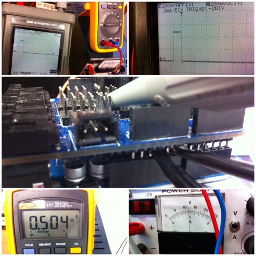
But then after some research about Arduino and unexpected resets and some voltage measurements the power adapter could not deliver the ampere needed for the stucked servo. After I changed the adapter with an other product that was in my old-cable box the problem was reduced, became rare and acceptable for this robot.
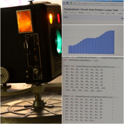
Then some smooth head rotation was implemented.
And the head turned again. With all the lights in action.
From a young automation apprentice I got some optocouplers. Using these and galvanic distinct the servo powerline and the Arduino powerline. The optocpoupler should send the PWM signals from the Arduino to the Servo by using flashing lights.
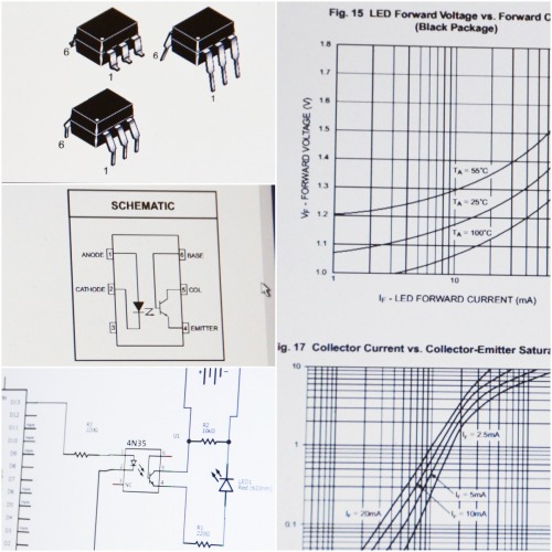
After successful LED testing the servo tests failed. The optocoupler seemed to be to slow.
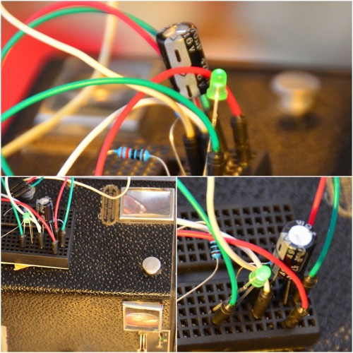
With the help of LMR the next approach was to insert condensers into the powerline of the servo. This reduced the problem again to an acceptable level.
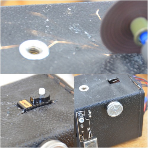
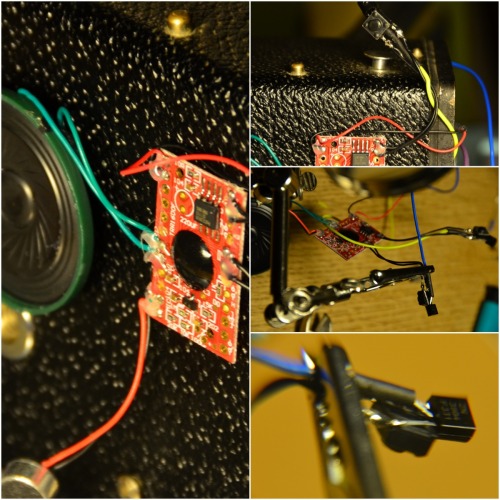
Next was to insert a 20-second sound module so the artist could record a scary deadly message the Spaghuzzinator has to say.
Fine. Done. Presented. Visitors liked it. We all had fun. Mission accomplished.
15 Minutes of Fame
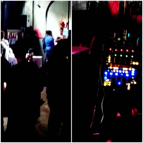
The Spaghuzzinator gets its 15 minutes of fame on the art exhibition.
Between paintings and other installations the Spaghuzzinator terminated whatever came across his lasers.
...and the visitors liked it.
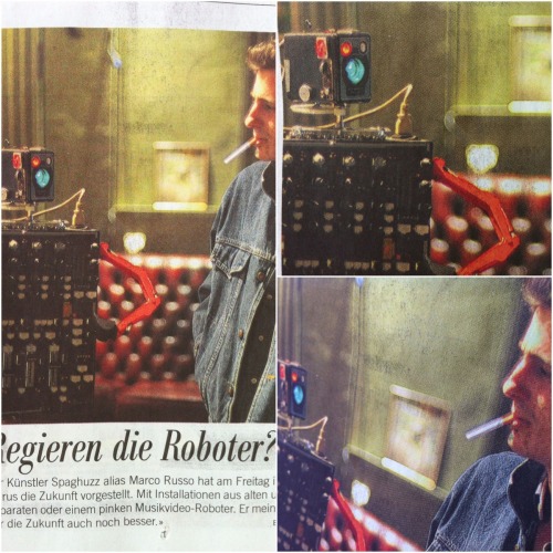
This robot got featured in the local newspaper together with the artist.
Alternative Solutions
This section contains possible alternatives I thought about...
- IR Compound Eye
- Tape Recorder Gearset
- Optocoupler for PWM transmission from the Arduino to the servo with separate power-supplies.
Further Readings
Servo Problems With Arduino - Part 1
"... its questionable whether an Arduino can reliably deliver power to even a single servo."
Start Here Robot
"Servos are sending a lot of electrical noise back on the line. The Yellow chip is a series of 330 Ohm resistors, that will reduce the amount of noise that is sent back to the microcontroller. It is simply straight lines across, with some resistance between, making the signals travelling both ways a little weaker. So it is there to protect the microcontroller."
Online Morse Code Converter
This robot says "Spaghuzzinator is here. You are terminated." in the morse language.
"... .--. .- --. .... ..- --.. --.. .. -. .- - --- .-. .. ... .... . .-. . .-.-.- -.-- --- ..- .- .-. . - . .-. -- .. -. .- - . -.. .-.-.-"
and it says "Fai schifo".
"..-. .- .. ... -.-. .... .. ..-. --- "
Smooth Head Rotation
Rotate the head along a minimum jolt mathematical function.
Optocoupler in Wikipedia
"The main purpose of an opto-isolator is "to prevent high voltages or rapidly changing voltages on one side of the circuit from damaging components or distorting transmissions on the other side."
Schema of Fast Optokoppler for PWM
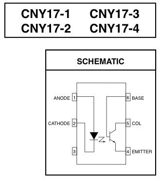
Can I Control a Servo via PWM from an Optocoupler
"Now I've added a 470μF electrolytic capacitor between the servo powerline (from Arduino again). The Arduino reset problem is gone."
De-Coupling
"When an otherwise good design works, but is erratic, unreliable or just goes crazy then nine time out of ten it is the power supply de-coupling. And you will find that the tenth time, turns out to be power supply de-coupling as well. So what is it, and why is it needed?"
20 Second Sound Module
"It'll eat 20 whole seconds of sound before barking it back at you..."
Terminates all life forms
- Actuators / output devices: servo
- CPU: Arduino Uno R3
- Power source: 12V Power Adapter
- Programming language: C
- Target environment: indoor, art, exhibition