


smartphone controlled robot with video streaming(imo)
hello guys..
this our poject IMO video controlled robot based on arduino using bluetooth hc-05..
for this robot we have used two smartphone ...
also this robot is controlled by a smartphone app..AND
video streaming is working on IMO..
Step 1: Components
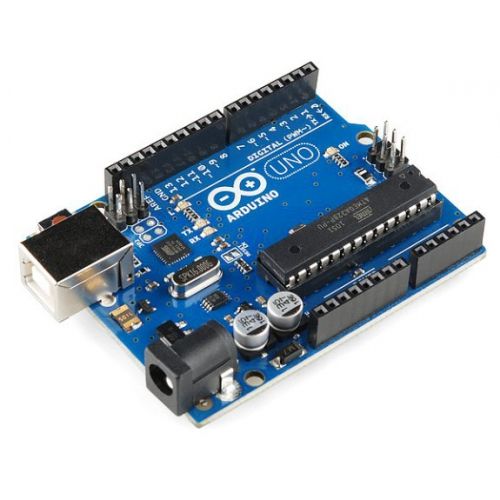
1:-ardunio uno
2:-motor driver l293d ic
3:-two android smartphone
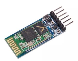
4;-bluetooth module hc-05
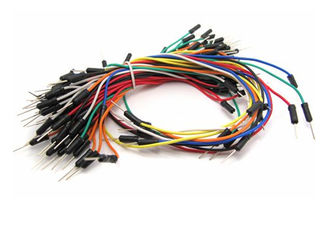
5:-jumper wires
6:-two dc motor
7:-one chassis
8:-two wheels with caster wheel
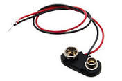
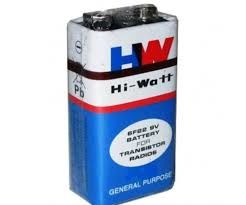
9:-9v battery or power bank
Step 2: Bluetooth Connection
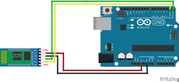
bluetooth module hc-05 ....
we have 4pins for connection to arduino..
vcc pin of bluetooth module ...................connect to +5v
gnd pin of bluetooth module ...................connect to gnd
tx pin of bluetooth module ......................connect to rx pin of arduino
rx pin of bluetooth module ........................connect to tx pin of arduino..
thats easy connection we have to do at 1st....
Step 3: If You Used As L293d Ic
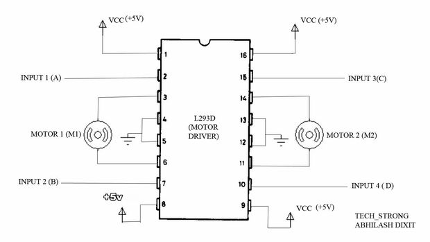
if you use l293d ic instead of l293d motor driver..
even its will be easy for connection...
. l293d ic have 16pin...
1,8,9 and 16 pin connect to +5v.
and 4,5,12,13 pin connect to gnd...
input 1,2,3 and 4pin is connect to arduino pin..
output is connect to left motor and right motor..
input 1 and 2 is connect for left motor..
and input 3 and 4 is connect for right motor..
Step 4: Circuit Diagram
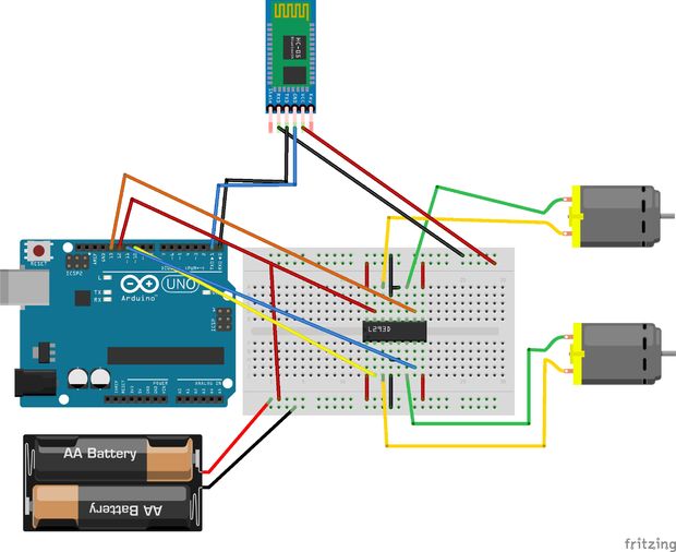
we have to connect 1st arduino with bluetooth module hc-05..
then ..........
motor driver l293d ic and arduino connection:-
we have to connect 1st arduino with bluetooth module hc-05..
then ..........
motor driver l293d ic and arduino connection:-
10,11,12 and 13 pin of arduino are connect to motor driver ..
10 pin of arduino is connect to 2pin of l293d
11pin of arduino is connect to 7pin of l293d
12 pin of arduino is connect to 10pin of l293d
13pin of arduino is connect to 15pin of l293d
Step 5: Connecting With Bluetooth and the Camera
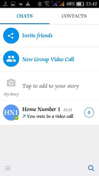
Now take another smartphones and install IMO app on both the mobiles. It is free over playstore Link-ihttps://play.google.com/store/apps/details?id=com....
install and open accounts on both the smartphones. It is free. Now start video call over both phones.Now put one mobile in the socket you just build on the chassis.
Now minimize the app in your other phone ,in which you will be installing my app .
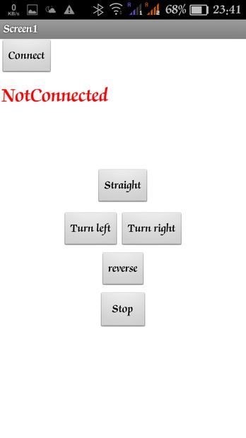
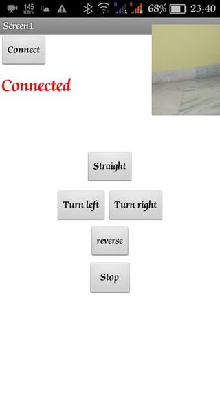
It will run still and it will be shown in a small window in the corner of your screen.You can drag it as well. See my screenshot given. Now install the app given.
The screenshots of the app are given.
Now first power up the whole thing and you should see the HC05's light blinking fast , Now open bluetooth in your phone and open the app and connect with the HC05 first( for first time use 1234 or 0000 as pairing code).Now if connected the light should blink slow ,if not try connecting again. Now press any of the buttons. Your car should move now.If not... see connections again and re-pair your HC05. So now your car is ready and your camera feature is also done.As you drive the video chat is on and you can see what is in front of the car!!! ...............

Step 6: Uploading the Code
at 1st..
remember that when uploading code in ardino..this time must be remove tx and rx pin of arduino..
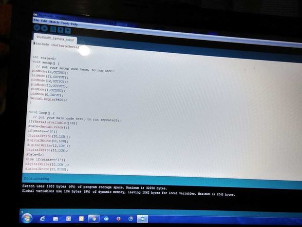
here the code..copy and paste the code...at 1st compile then upload to arduino...
#include <softwareserial.h>
int state=0;
void setup()
{ // put your setup code here, to run once:
pinMode(10,OUTPUT);
pinMode(11,OUTPUT);
pinMode(12,OUTPUT);
pinMode(13,OUTPUT);
pinMode(1,OUTPUT);
pinMode(0,INPUT);
Serial.begin(9600); }
void loop()
{ // put your main code here, to run repeatedly:
if(Serial.available()>0){ state=Serial.read();} if(state=='0'){ digitalWrite(10,LOW ); digitalWrite(11,LOW); digitalWrite(12,LOW ); digitalWrite(13,LOW); state=0;} else if(state=='1'){ digitalWrite(10,LOW ); digitalWrite(11,HIGH); digitalWrite(12,LOW ); digitalWrite(13,HIGH); /*right*/ state=0;} else if(state=='2'){ digitalWrite(10,HIGH ); digitalWrite(11,LOW); digitalWrite(12,HIGH ); digitalWrite(13,LOW); /*left*/
state=0;} else if(state=='3'){ digitalWrite(10,HIGH); digitalWrite(11,LOW ); digitalWrite(12,LOW ); digitalWrite(13,HIGH ); state=0;} else if(state=='4'){ digitalWrite(10,LOW); digitalWrite(11,HIGH ); digitalWrite(12,HIGH ); digitalWrite(13,LOW ); state=0;} }
Step 7: Result
so guys.
here this below link help you to build this project easily on you tube of our channel s_r tronics........
https://www.youtube.com/watch?v=ynNQok8e7r0
so..subscribe our channel and do likes and comment also....
next project coming soon..
and stay tuned with us...