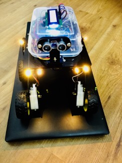
Voice Control Robot
Robot using your smart phone just say commands like move forward, move back.This motor driver can be controlled by simply applying a logic 0 or 1 to the direction pin for that motor and a PWM signal to the speed pin. In this way, the speed and direction of four separate motors can be controlled independently from only 8 GPIO pins. 4 Channel Motor Control Unit Designed originally for chassis this driver PCB is ideal for any small robot using either Omni or Mecanum wheels. Current sensing for each motor allows the processor to determine if a motor has stalled or is under excessive load.
Features include:
• 4x low resistance FET “H” bridges.
• Each channel rated for 4A stall current
• Easy to use control logic.
• Current monitoring for each channel.
• Quadrature encoder mixing circuitry.
The PCB has two power connectors. One is +5V for logic (Vcc) and one for the motor power supply. The motor power supply should not be connected without first connecting the +5V for logic. This device is rated for a maximum motor supply voltage of 12V. Exceeding this voltage may permanently damage the device. The encoder mixing circuit: Unlike most motor controllers this PCB includes 4 mixing circuits for use with up to 4 quadrature encoders. The mixing circuit takes the 2 inputs from a quadrature encoder and mixes them into a single output. Note that the interrupt output changes state when either input changes.
The encoder mixing circuit:
Unlike most motor controllers this PCB includes 4 mixing circuits for use with up to 4 quadrature encoders. The mixing circuit takes the 2 inputs from a quadrature encoder and mixes them into a single output. Note that the interrupt output changes state when either input changes.
This allows a single interrupt pin to monitor both inputs of a quadrature encoder. Because the interrupt output is twice the frequency of either input it also allows speed and distance to be measured with twice the resolution. Current output: Each channel has a current sensing circuit. The output of this circuit is approximately 1V for each amp the motor draws (5V maximum). This output can be connected directly to the analog input of any 5V micro controller. Control logic: The built in control logic allows each motor to be controlled by 2 pins. Driving the direction pin high or low will cause the motor to run forward or reverse. The PWM pin is used to control the motor speed. When this pin is low, the motor is off. When this pin is high the motor is at full power. To vary the speed of the motor this pin must be Pulse Width Modulated. Motor output: Each channel has a motor output socket. Connect any 4.5V –12V DC motor with a stall current of less than 4.5A to these pins. Exceeding 4.5A on these pins may permanently damage this device.
The program of voice control robot.
Hardware of Robot 2.0
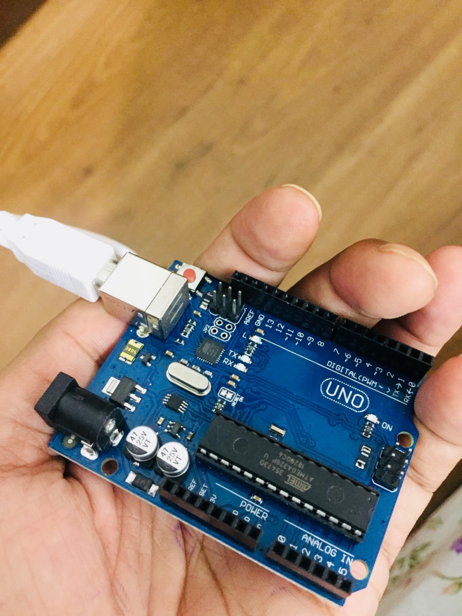
1) Microcontroller
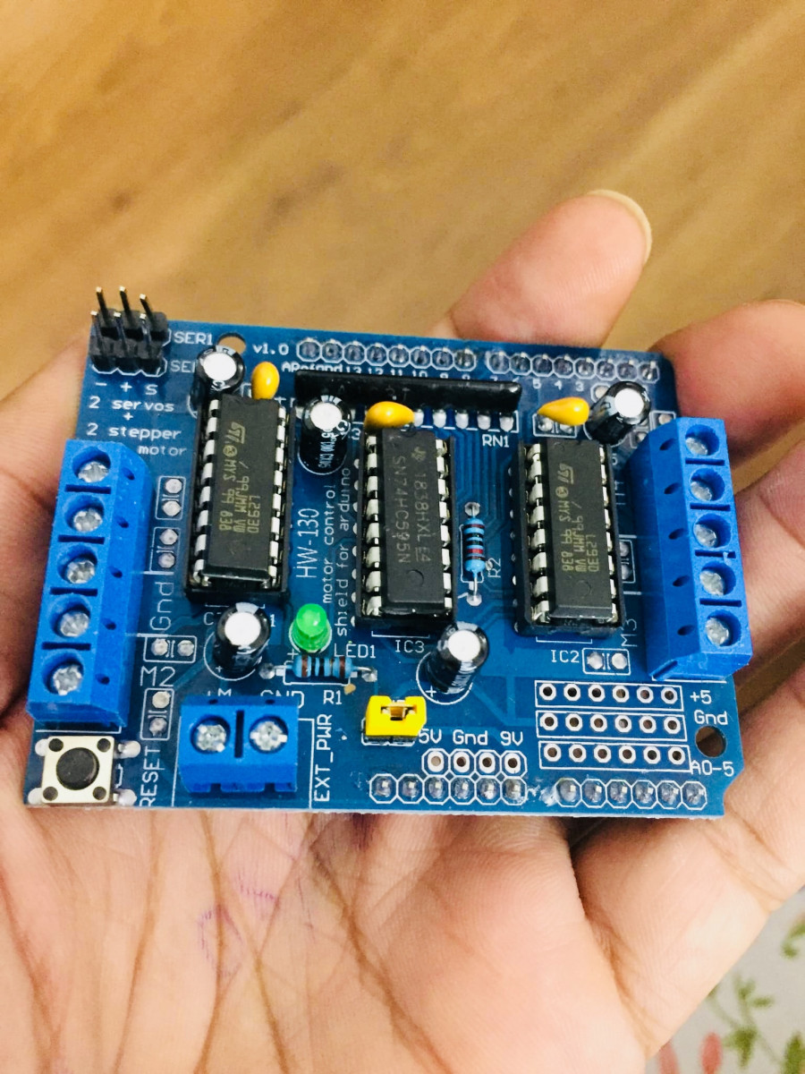
2) Motor Driver
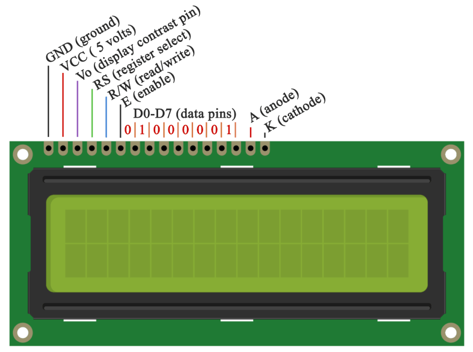
3) 16x2 LCD Display (Embedded System)
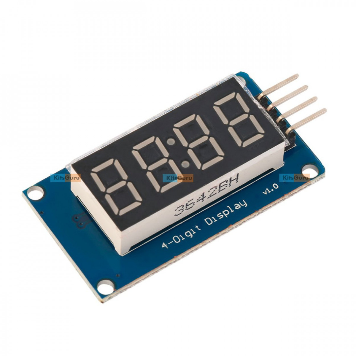
4) Four bit digital display module.
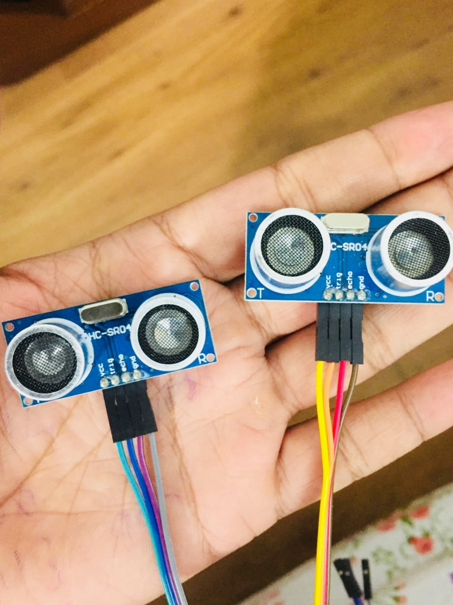
5) Ultra sonic sensor
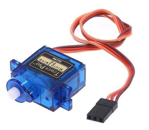
6) Servo motor
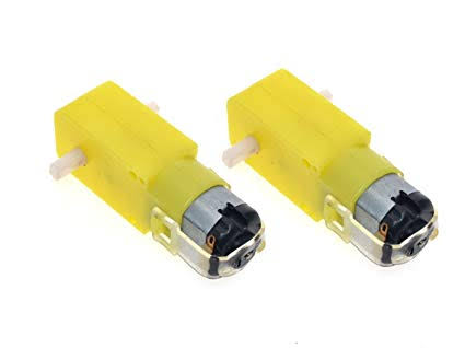
7) DC Motor 6 pieces
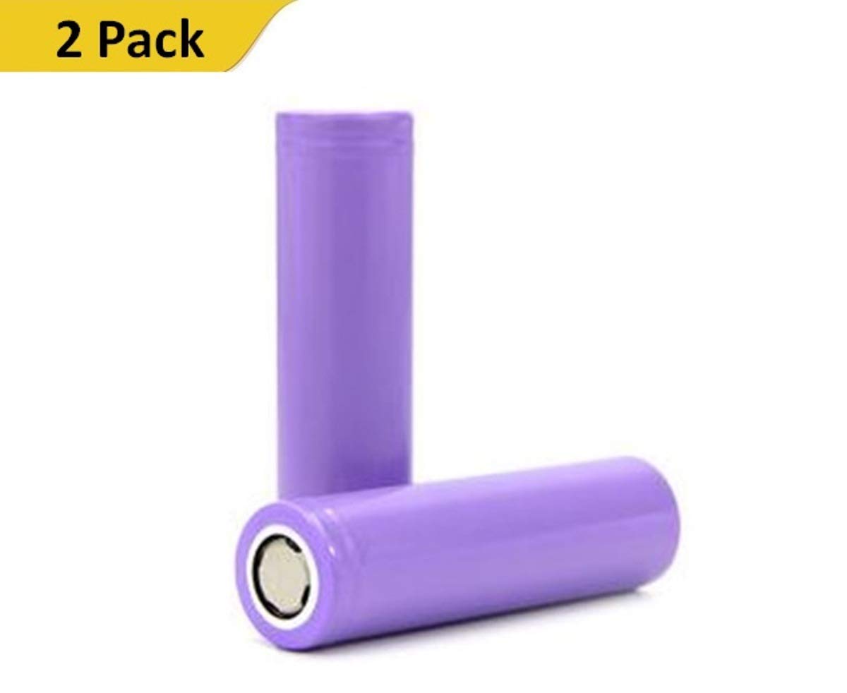
8) Battery 3.7V 2200 Mah Lithium Ion Rechargable
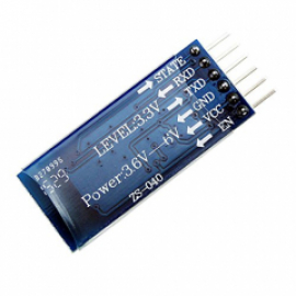
9) Blutooth HC-05
Few lines voice control and ultra sonic sensor control Program for Microcontroller.(Full program is not mentioned)
#define CUSTOM_SETTINGS #define INCLUDE_VOICE_RECOGNIZER_SHIELD #define INCLUDE_TERMINAL_SHIELD /* motor driver pins */ #define DIRECTIONA 4 #define MOTORA 5 #define DIRECTIONB 7 #define MOTORB 6 /* Include 1Sheeld library. */ #include <OneSheeld.h> /* Voice commands set by the user. */ const char moveCommand[] = "move forward"; const char leftCommand[] = "left"; const char rightCommand[] = "right"; const char backCommand[] = "move back"; const char stopCommand[] = "stop"; /* go forward function */ void forward() { digitalWrite(DIRECTIONA,0); digitalWrite(DIRECTIONB,1); analogWrite(MOTORA,200); analogWrite(MOTORB,200); }//end of forward function /* go back function*/ void back() { digitalWrite(DIRECTIONA,1); digitalWrite(DIRECTIONB,0); analogWrite(MOTORA,200); analogWrite(MOTORB,200); }//end of back function /* turn left function */ void left() { digitalWrite(DIRECTIONA,0);
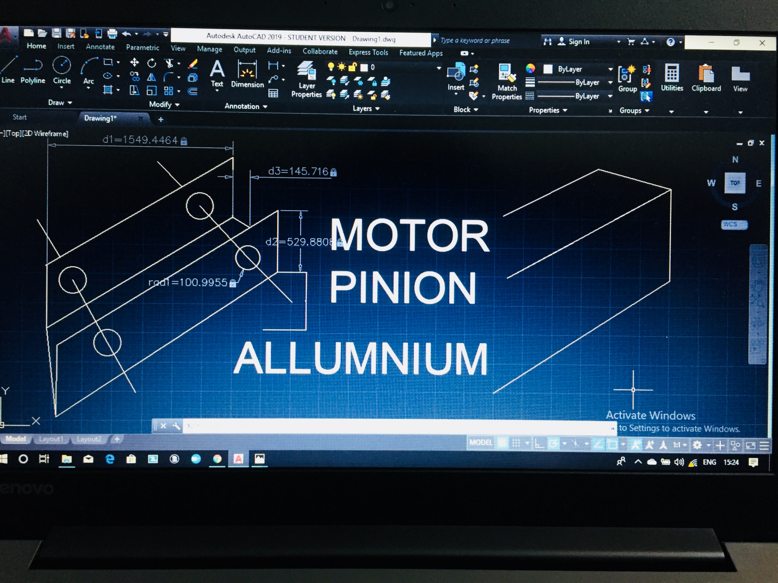
Working on Six Wheeler Robot Alluminium Frame.
We are now designing our next robot in CAD 2019 software alluminium frame six wheeler robot.