


My main requirements to the project are as follows:
- It must have an appearance that identifies it as a dog, with the right proportions.
- It must be able to move and act as a dog, confining it to the limitations of real canine.
- It must be (eventually) Autonomous and self learning.
The projects phases of development: (subject to change)
1. Designing the physical appearance of the robot and deciding its proportions and size
2. Figuering out what components I will be using, how and if they are the right fit for my model.
3. Redoing 2. As I find that the stuff i bought is not suitable. Mostly because i got too eager and didnt do the proper research before checking out.
4. Creating a kinematics model and coding the basics.
5. Further development (Artificial Intelligense, sensors, motion tracking, perception of surroundings etc.
The first steps
This 'learning by doing' sorta stuff has once again proven itself to be an "exciting" deal. I have barely started and already iv'e shot myself in the foot atleast a dusin times. I do promise to let you know about all my mistakes, not as to scare other newbs but as a reminder that you are not alone in your eternal fails.
So.. onto the modelling part of things. I'm using Fusion360 for all my 3d modelling, main reasons being that it is very diverse in its capabilities, has great support both in the community and directly from the devs, and its free for hobbyists. Yay!.
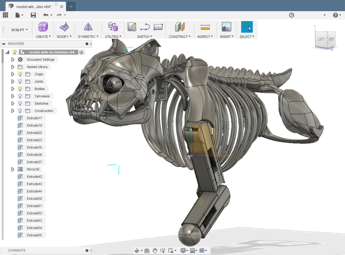
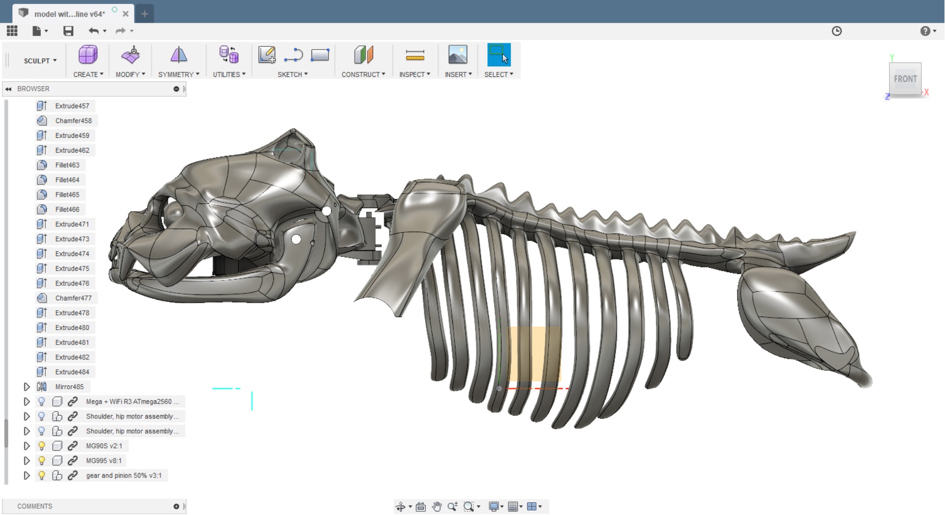
I am in no way an artist, so I needed a referense picture to start things off. I searched google til it got sore and found many candidates, however, as fur is kinda hard to both model and 3dprint, and smooth models allready having been done in a great variety, I decided to go with a motive that I hadnt encountered more than maybe a few times - a skeleton. The goofiest canine skeleton i could think of had to be an english bulldog, so this is what i went with.
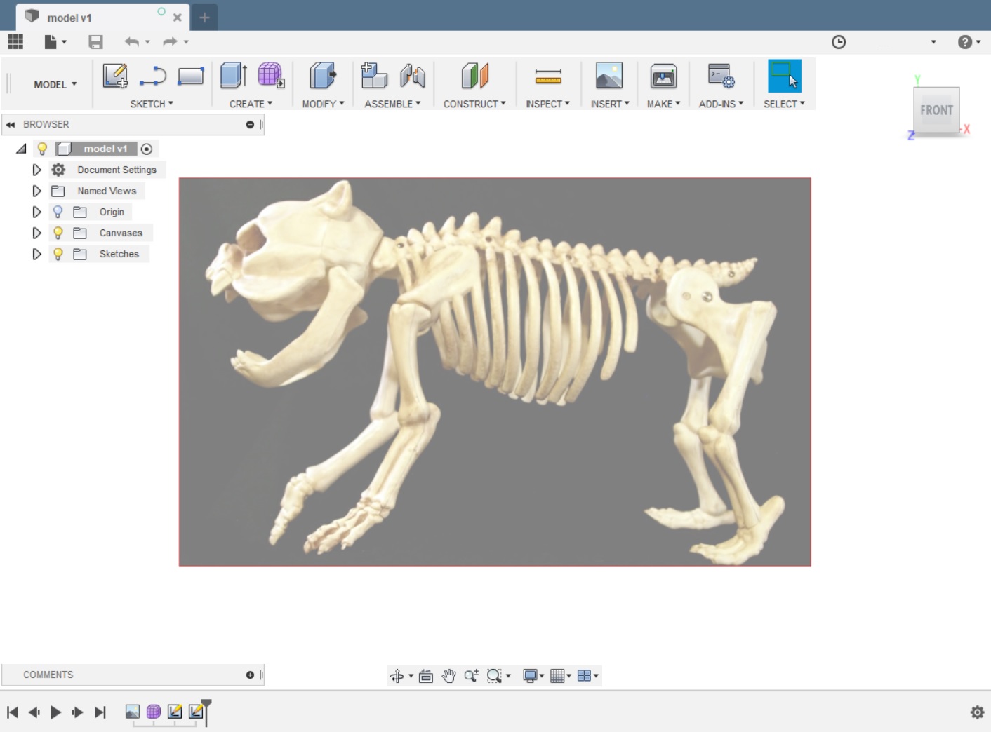

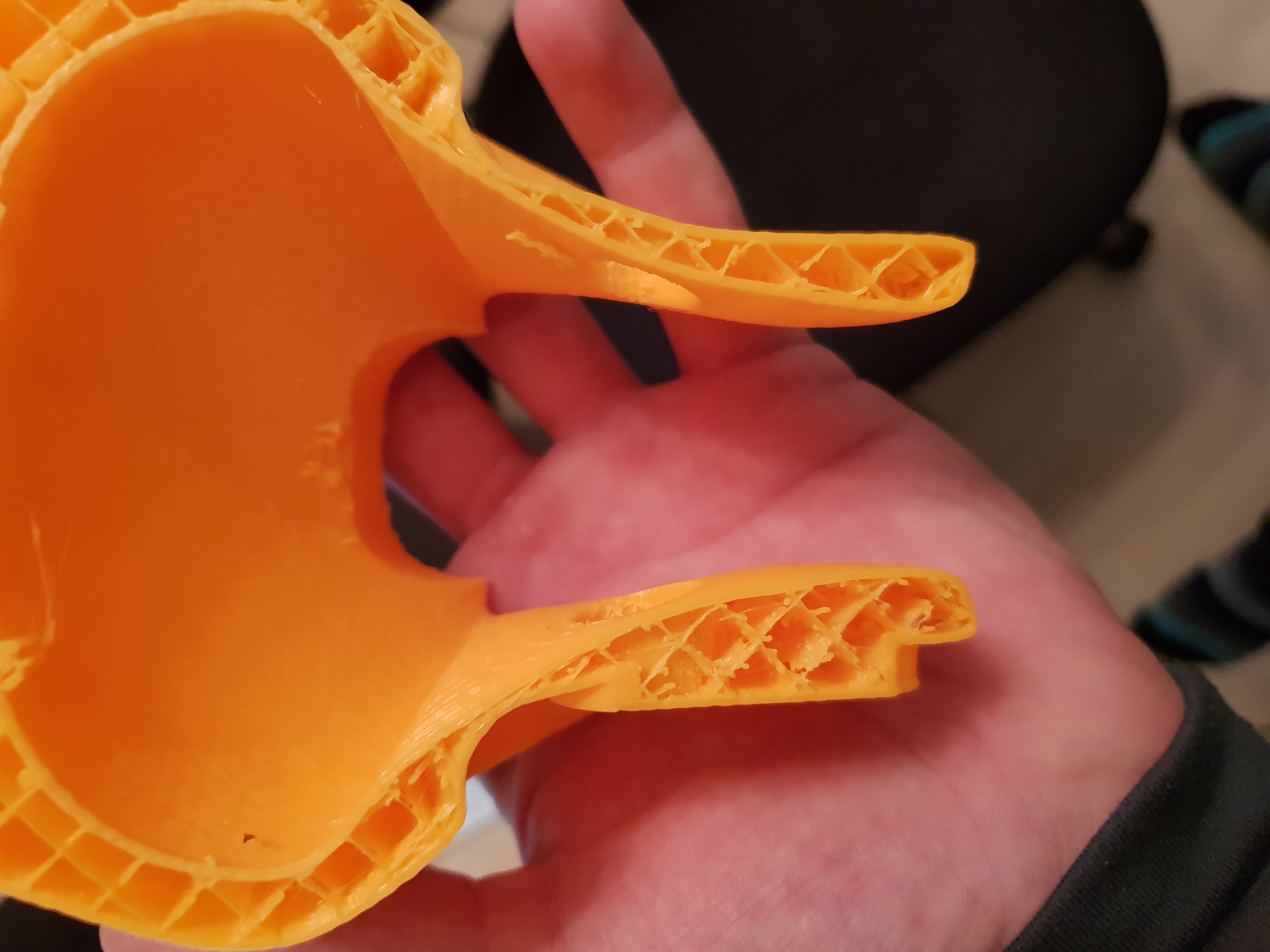
The canvas was only used in the early modeling stages, to get a rough model at the correct scale. I then started modeling the head, and this is where i made my first mistake by modeling the feature as a box and not a flat surface. This gave me quite the headacke when i later had to hollow out the skull, had I used a flat surface, I then would have been able to shell it and get a uniform thickness all around and not have to sit and drag points for hours. Lesson learned!
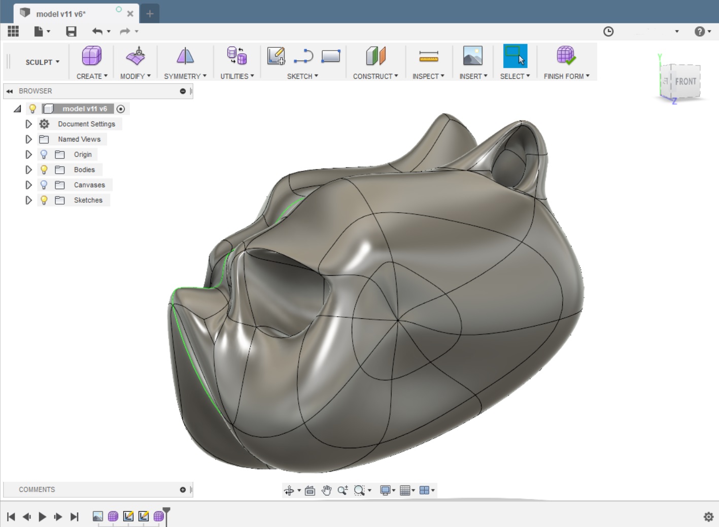
^The early beginnings.
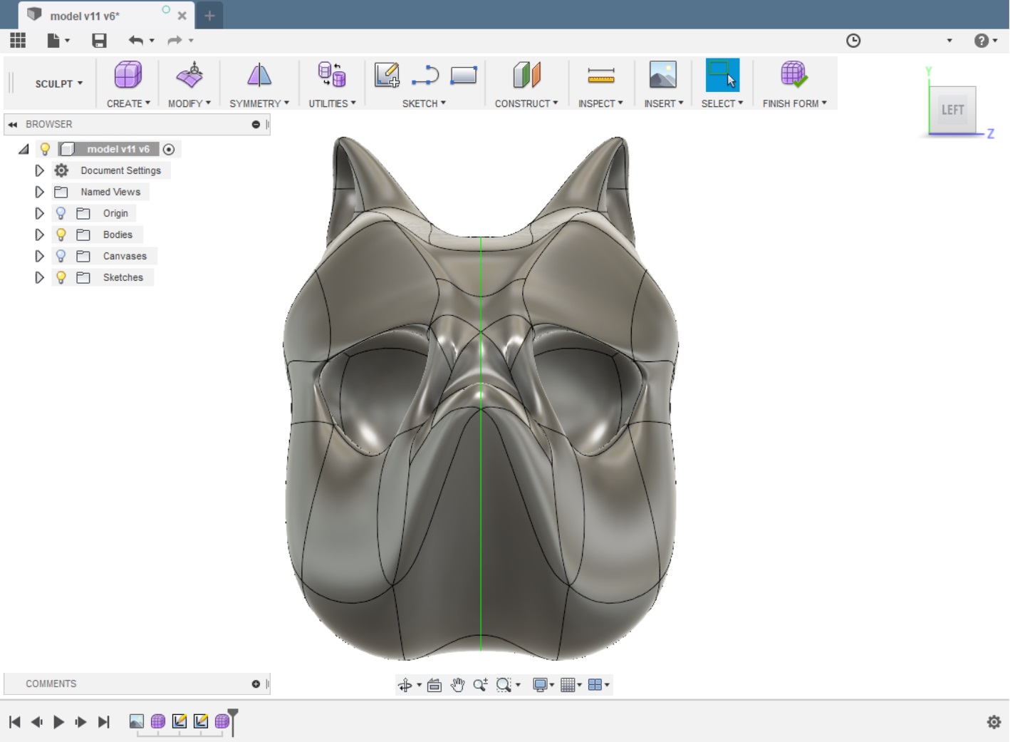
And many many hours later.. We have a skullfish!
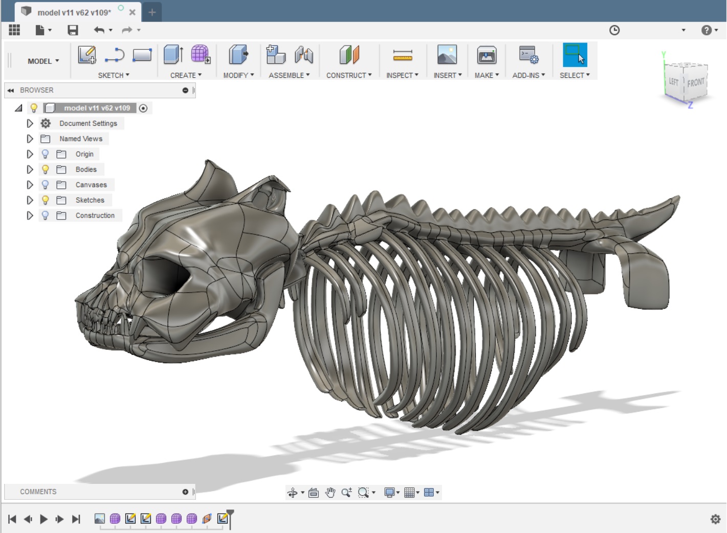
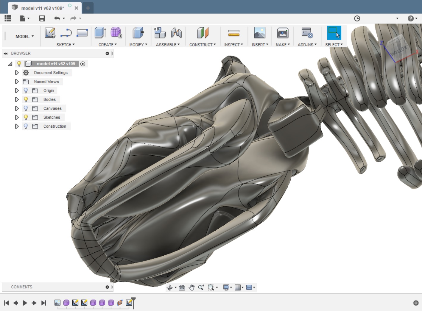
^Here you see what i mean about the hollowing pain. Because i was a complete newb with fusion, at this point the model is sitting at 25+ hours of work, i had sooo many back and forths, that i actually considered starting over at multiple points. Fusion chrashing now and then, and me not having saved my recent work definetly didnt help either.
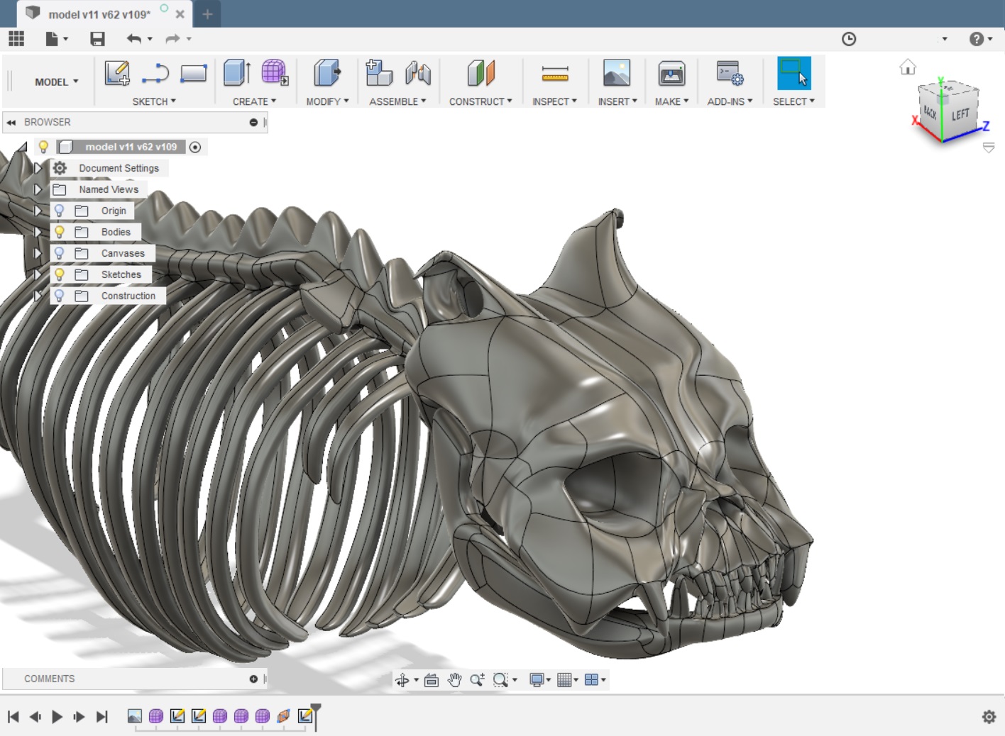
Another 10 hours of modeling later and:
the skull has been hollowed, shoulders and pelvis added, and i mounted the upper leg model on all 8 joints
At this point I decided to do a testprint of the skull, to get an idea of the size and level of detail before moving into modeling other components, such as servos and brackets.
My printer is a modded Tevo Tarantula btw.
This was the result, my happiness and patience started to return.
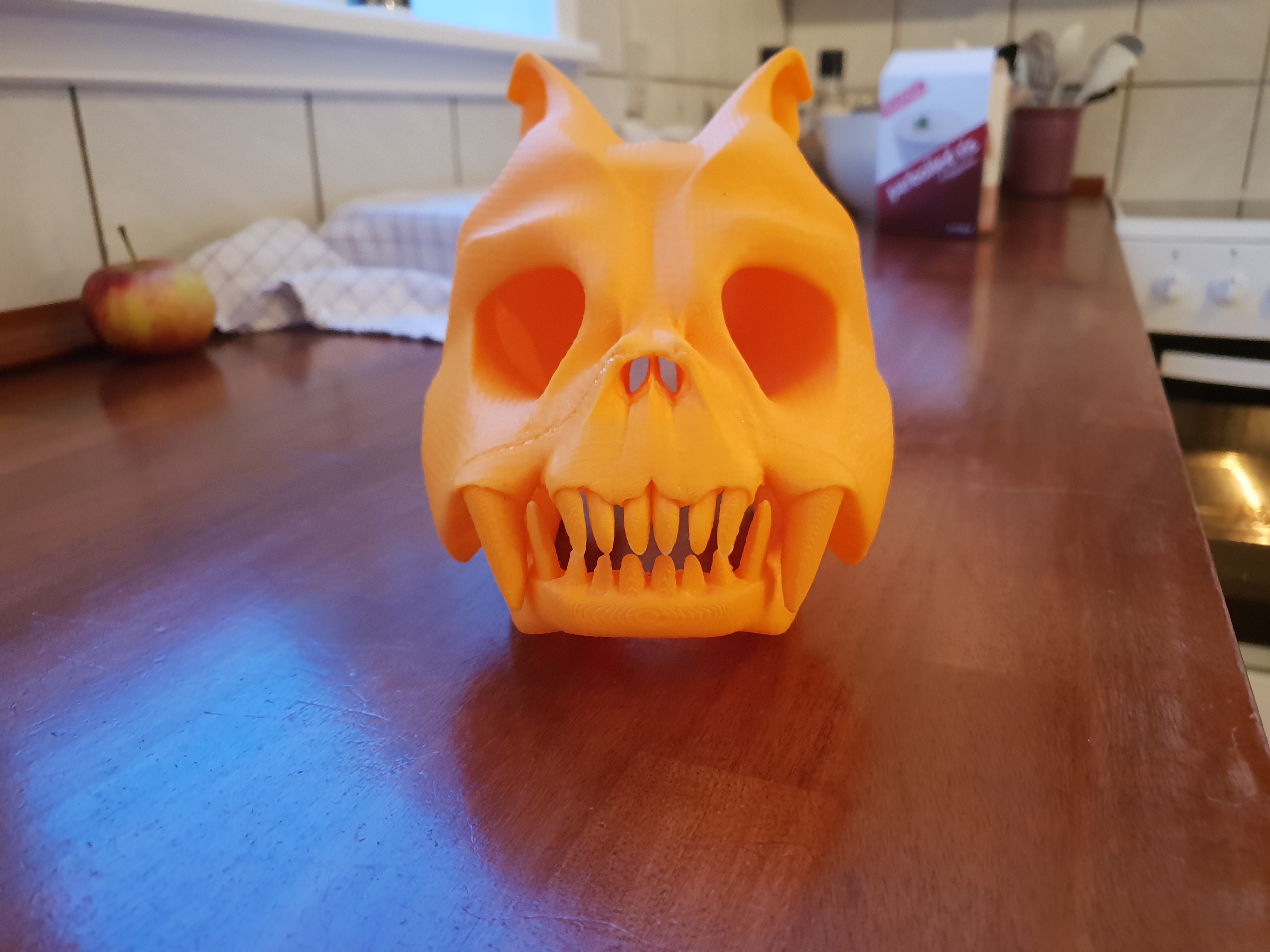
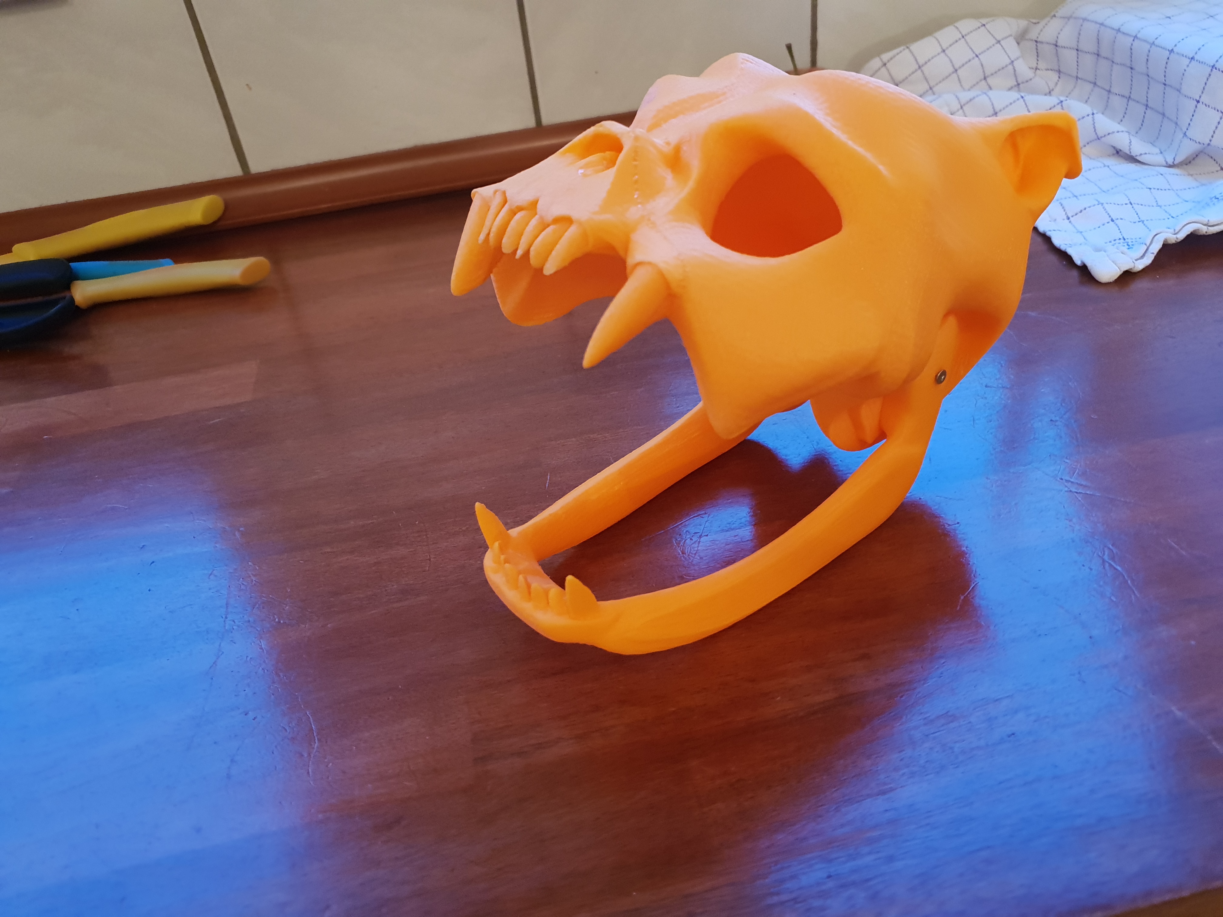 Looking great!
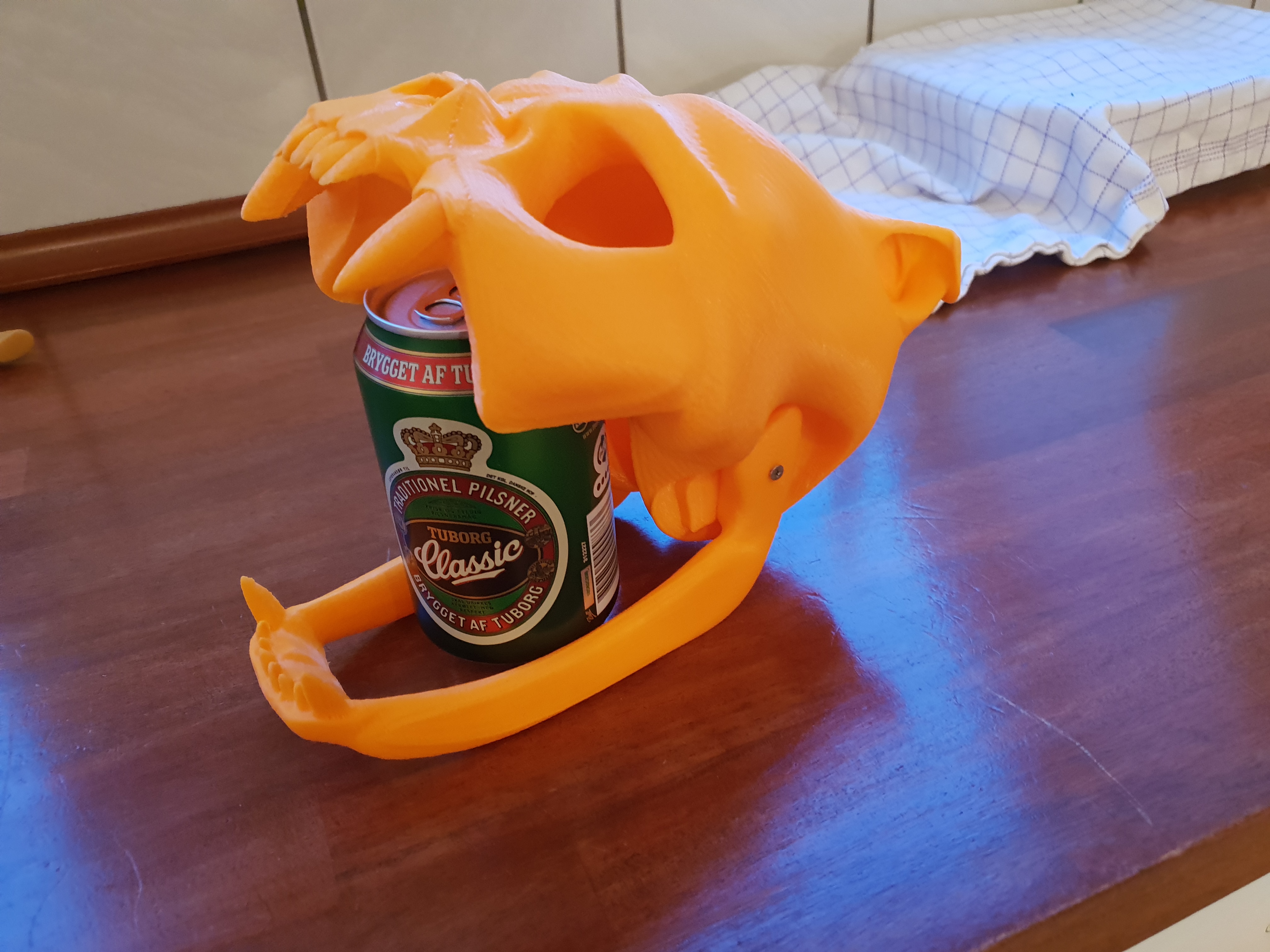 ^Beer for scale
You may notice a seam above and around the schnaut, my printer software apparently havent been set correctly on the z-height limit. There is plenty of actual travelspace left on the printer, but I had to reprint the nose and teeth, to then glue and weld onto the rest of the skull.
below is another fail, one of many, where i forgot to mirror the model.
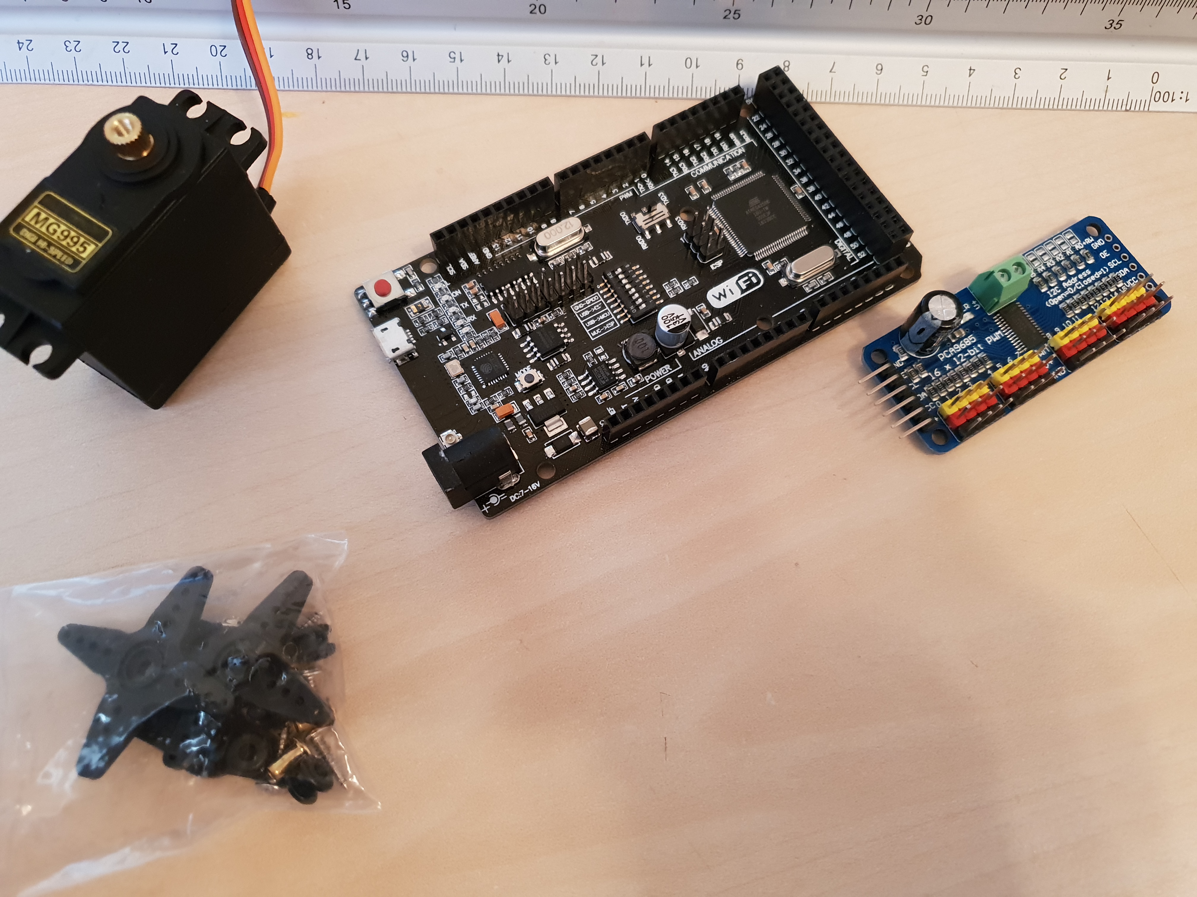
The next step was to start modeling som of the components that I needed to accomodate in the skull and the ribcage. I like the idea of having WiFi built into the arduino so I went and ordered a Wemos Mega +WiFi R3 Atmega2560+ESP8266 and a bunch of Tower Pro MG955 clones, along with a few 16 channel 12-bit PWM/Servo Driver-I2C interface boards. I have noticed that people are getting mixed results trying to get the Wemos WiFi working, but that wil be a headacke for later. It turned out i had plenty of issues for now.
Moar pictures pleease..
I ordered 22 of the servos and this is where i made my first of the more costly mistakes.

Did anyone spot the problem????
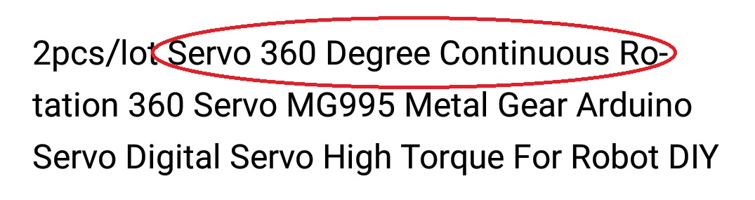
FOR FROG SNACKS!!!
Being a newb i didnt know that 360 servos can not be controlled angular, and consequently i didnt notice the issue until i started some testcoding. So, i searched around and thought long and hard about a solution, this is what i settled on.
I bought 30 of these little buggers
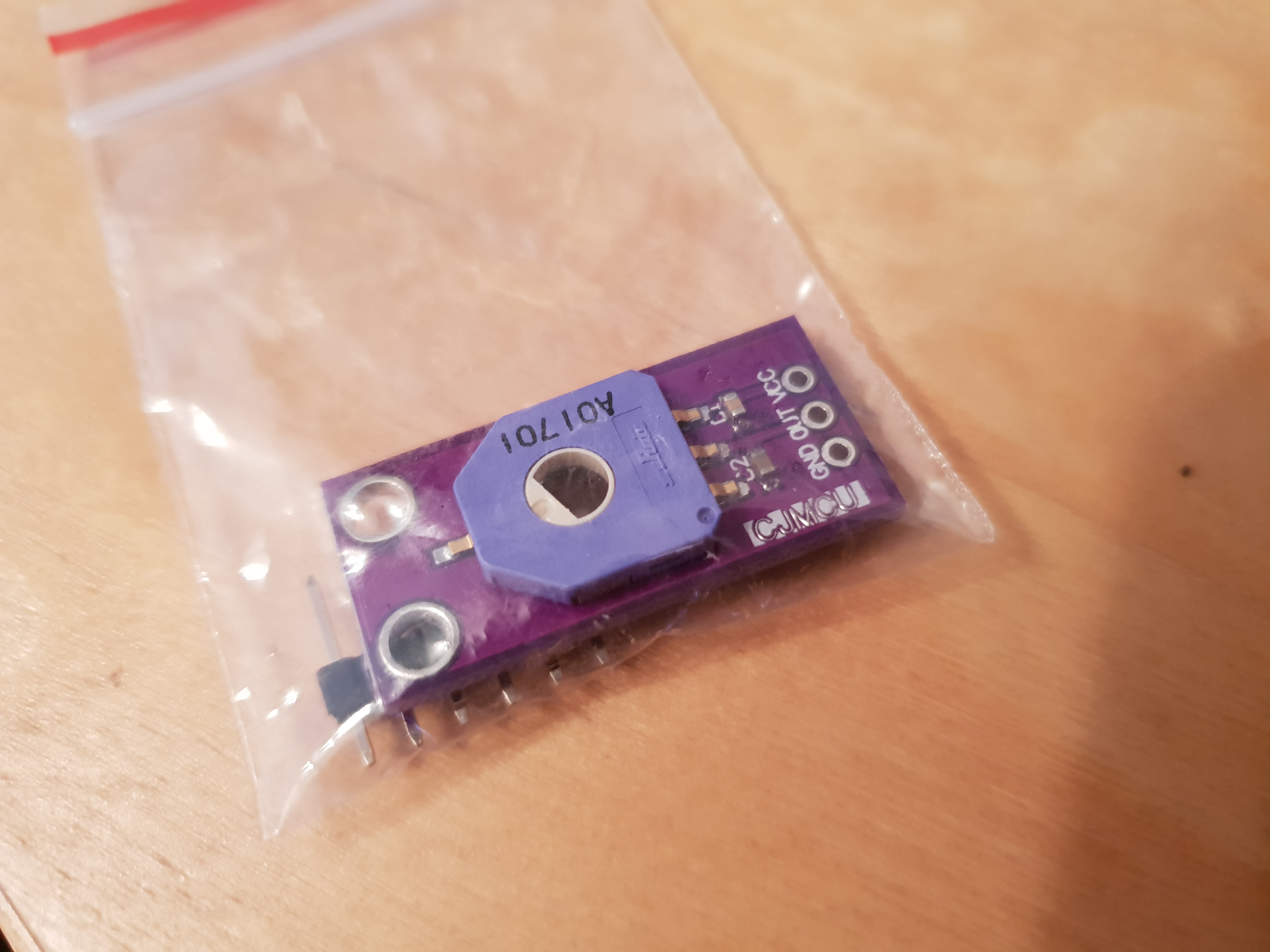
They are CJMCU-103 Rotary angle sensors, or, just a bunch of small potentiometers with a 270 degree range.
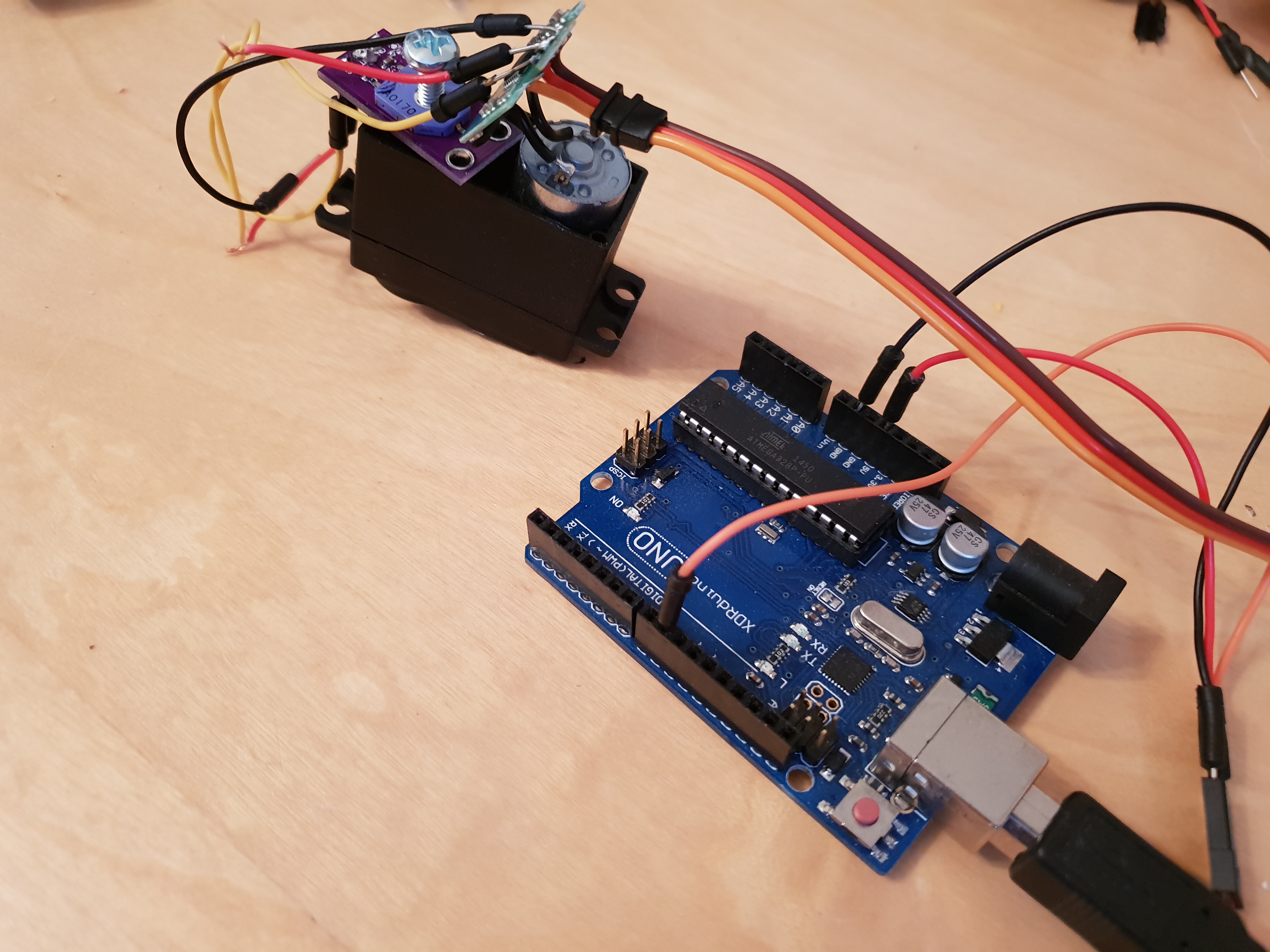
This is my setup trying to solve the problem. It did work to some extends, and i did manage to sort of get some control, but with neither the servos, nor the sensors having any kind of end stops, it was very unreliable. I am sure this could work, but the prospect of having to do 20+ servo convertions, and the uncertainty of success, the idea has been shelved and i will just use the servos as they are for testing purposes, adding some endstops to keep the machine from breaking itself.
Also, I have since decided to instead go with geared DC motors for all the major joints, servos are noisy and i am just not sure they can handle the forces applied during faster movements.
So, KBO it is.
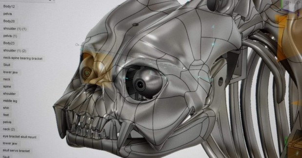
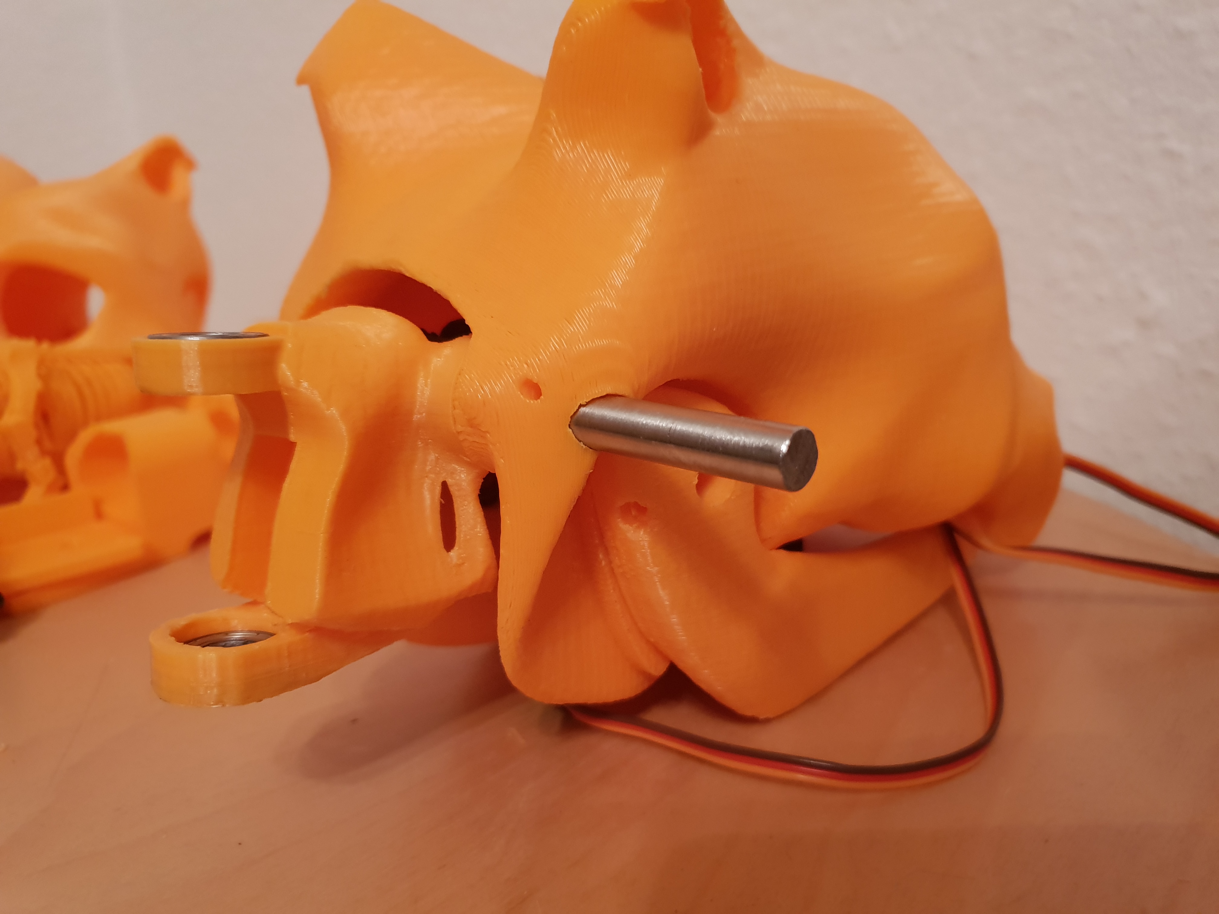
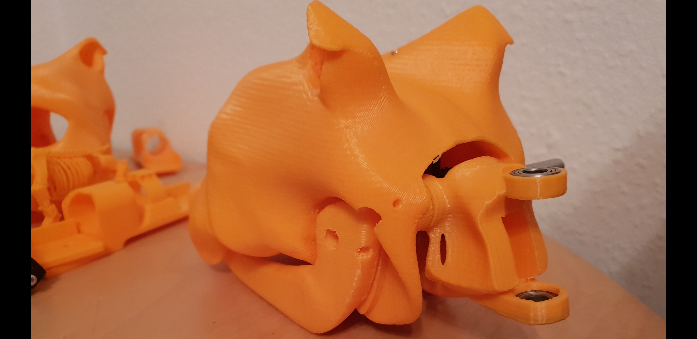
I re-did the upper leg because it looked too chunky, and then started the process of creating all the components to get the skull ready for V1 prototyping. This includes: Brackets, bearings, axles, servomockups, bearing slots in the joints, screwholes, animatronic eyes etc. etc.
.
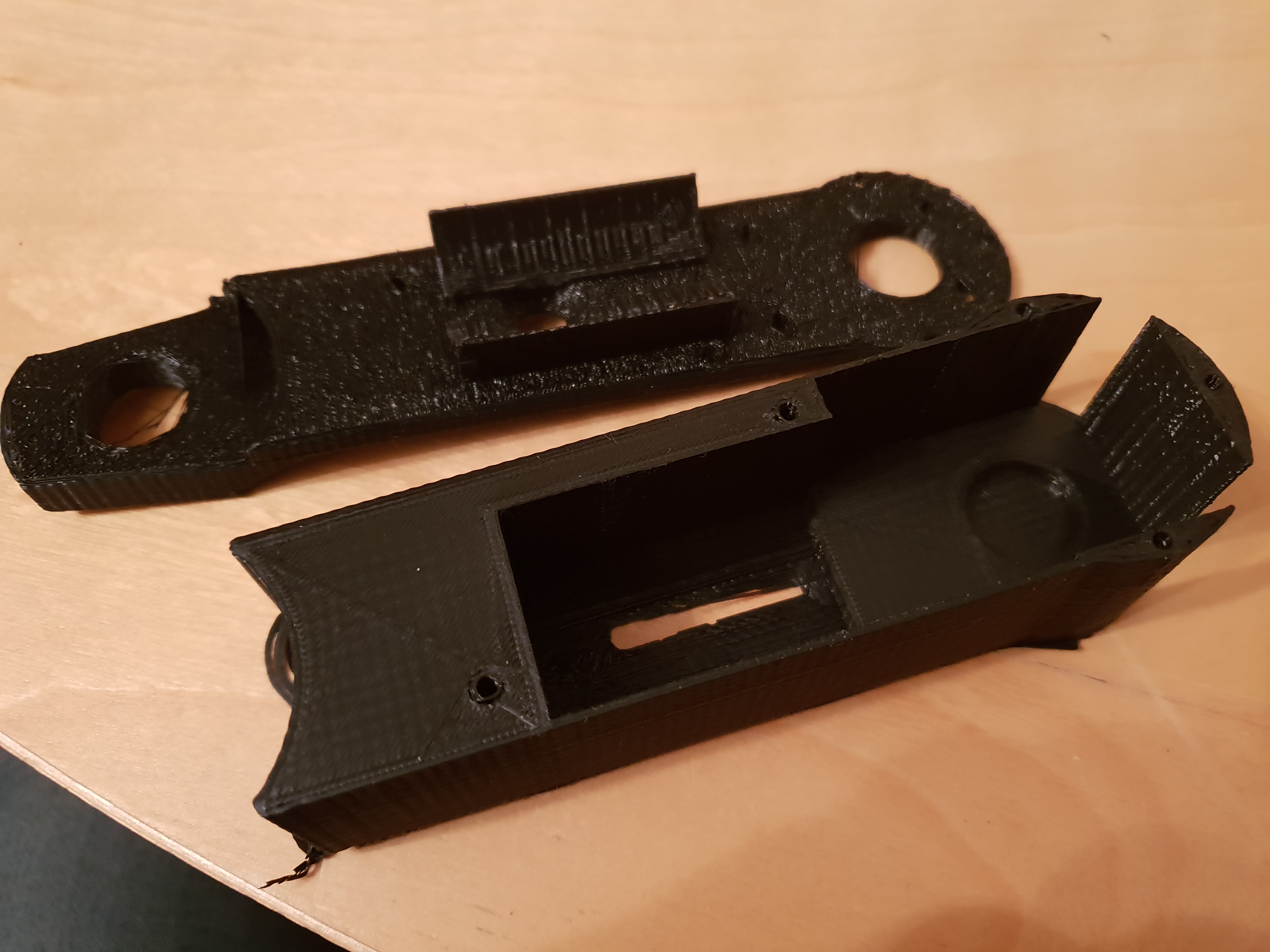
The model now sits at 75+ workhours, and finaly I can get on with printing the first parts of the prototype. I took notice of the mistakes made earlier and printed the skull in 2 parts to avoid more waste plastic.
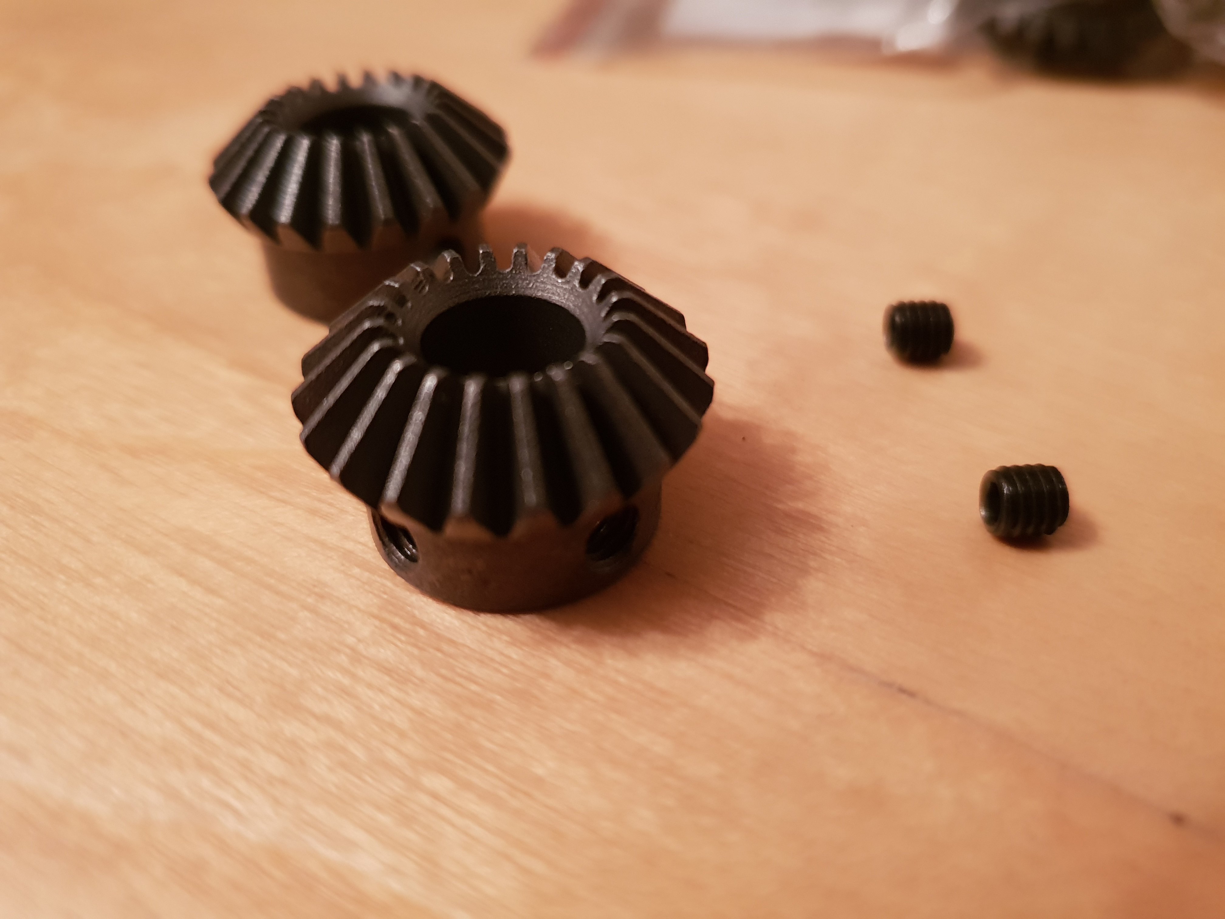
Also I made some gears for the jaw and neck servos, however the teeth are a little on the small side and even though I printed them with a 0.2mm nozzle, the precission isnt great, not bad, but definetly not the best. So I ordered some steel bewel gears from chinaexpress, still waiting on those.
Lots of printing and tinkering later and... Here we are!
.
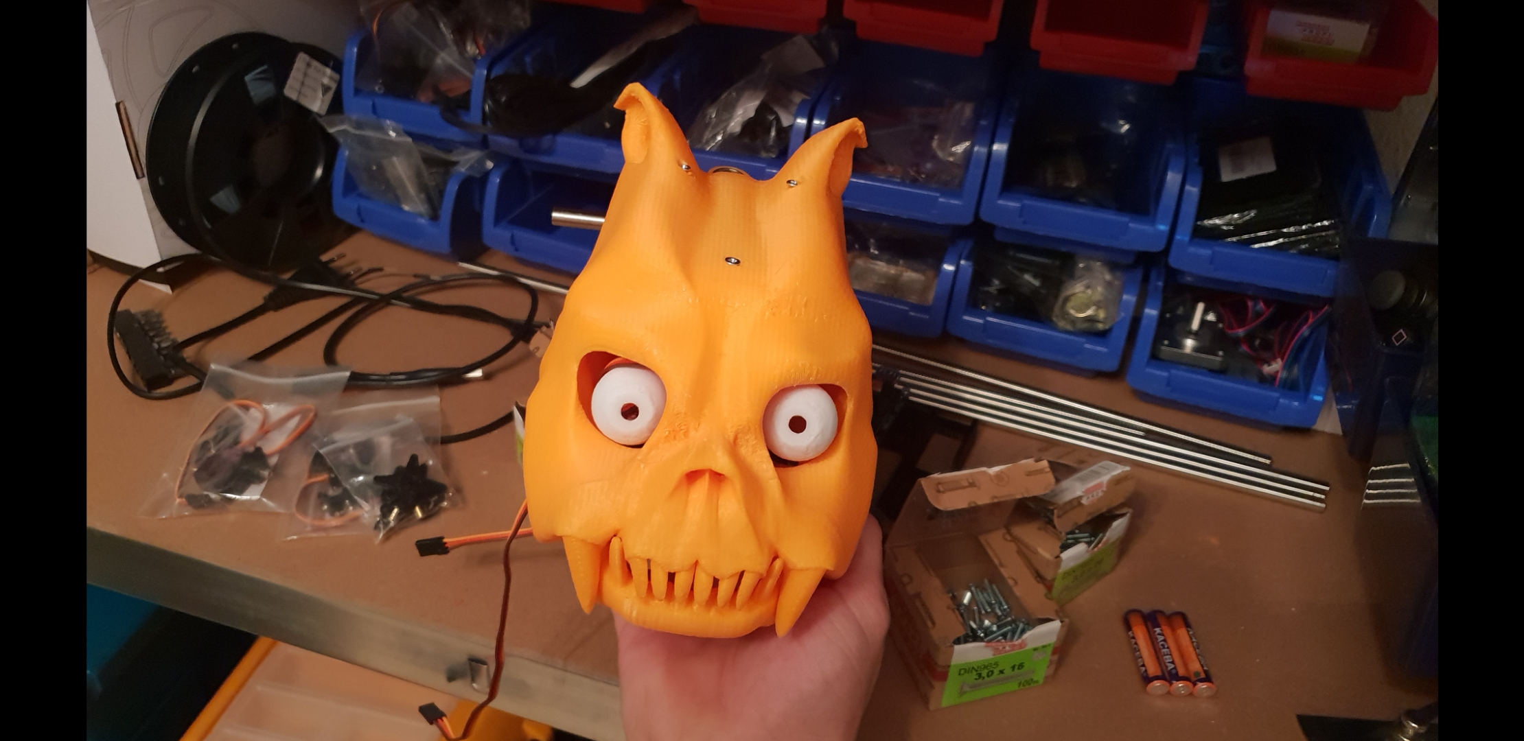
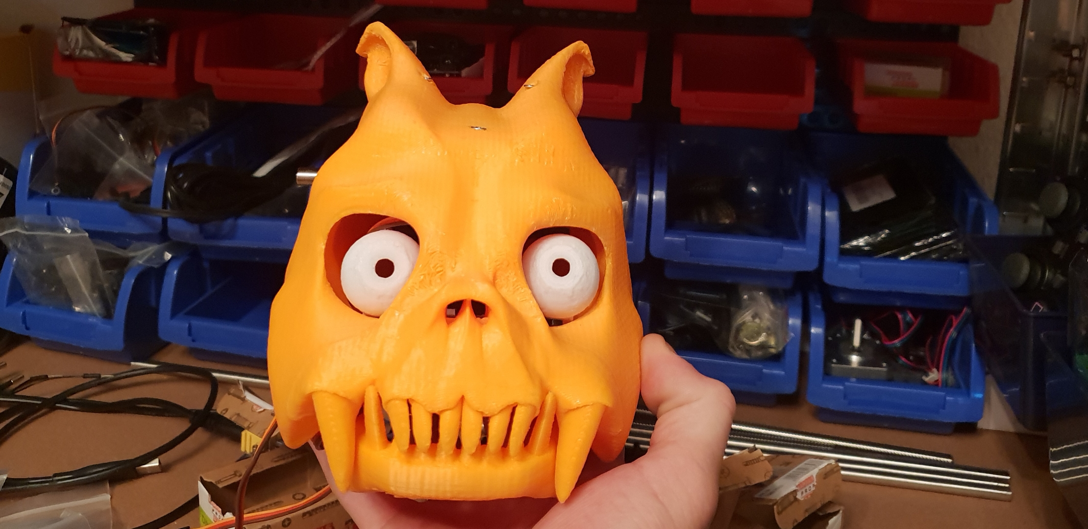
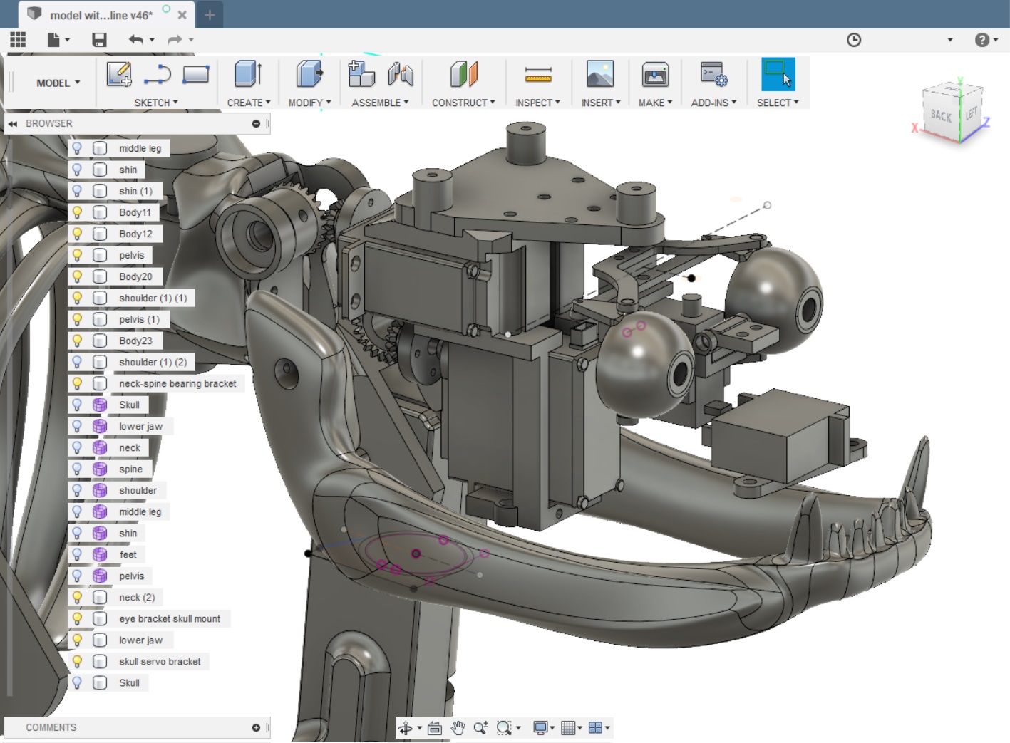
Skull Prototype (almost) ready for coding!. The eyes do have some discussions about clearance with the large servobracket, but that is an easy fix and a bit of therapeutic modeling should solve it.
This is where i am at, please feel free to give me your feedback on the project, any advice and ideas will be taken kindly.:)
Stay tuned....
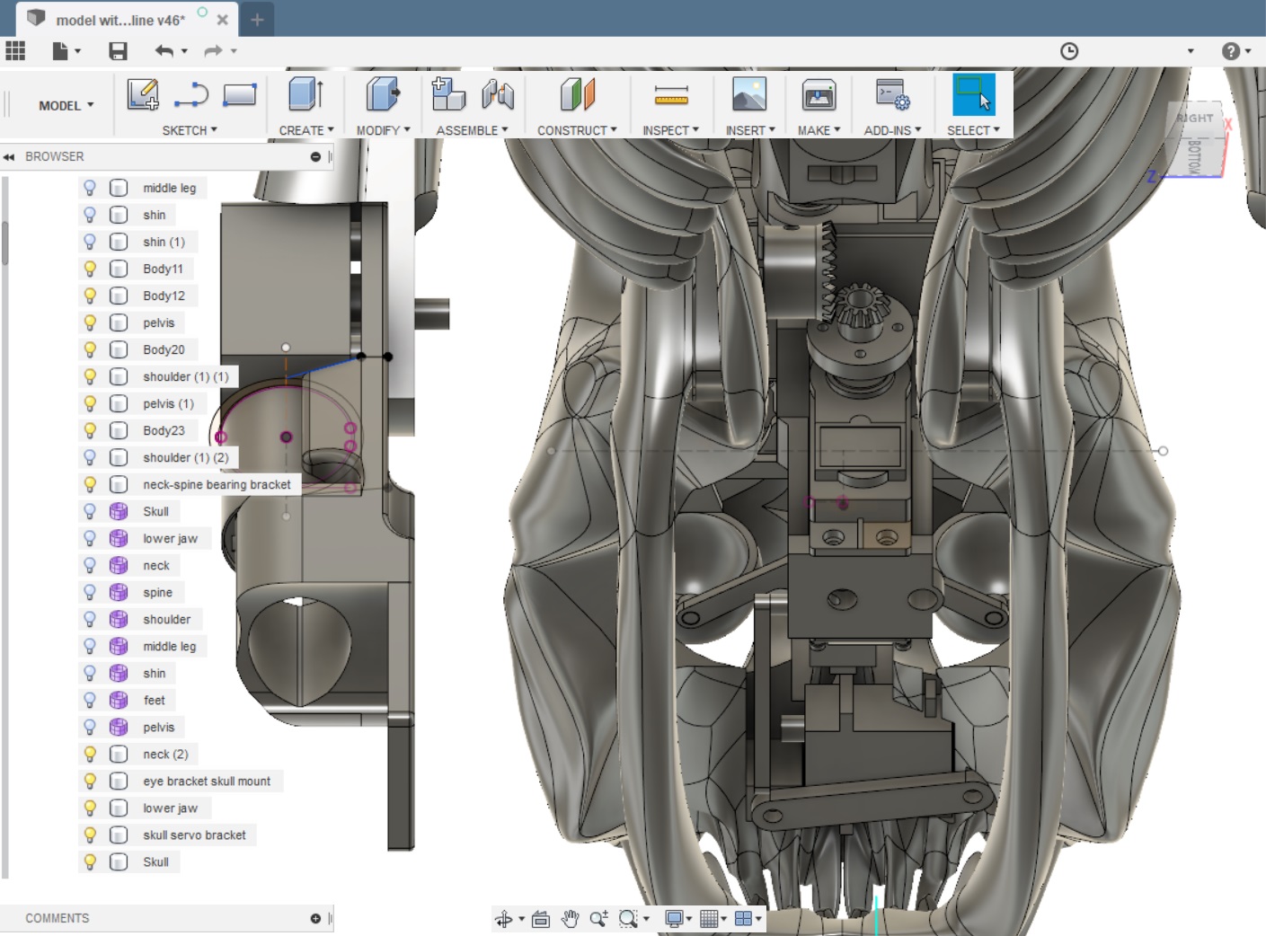
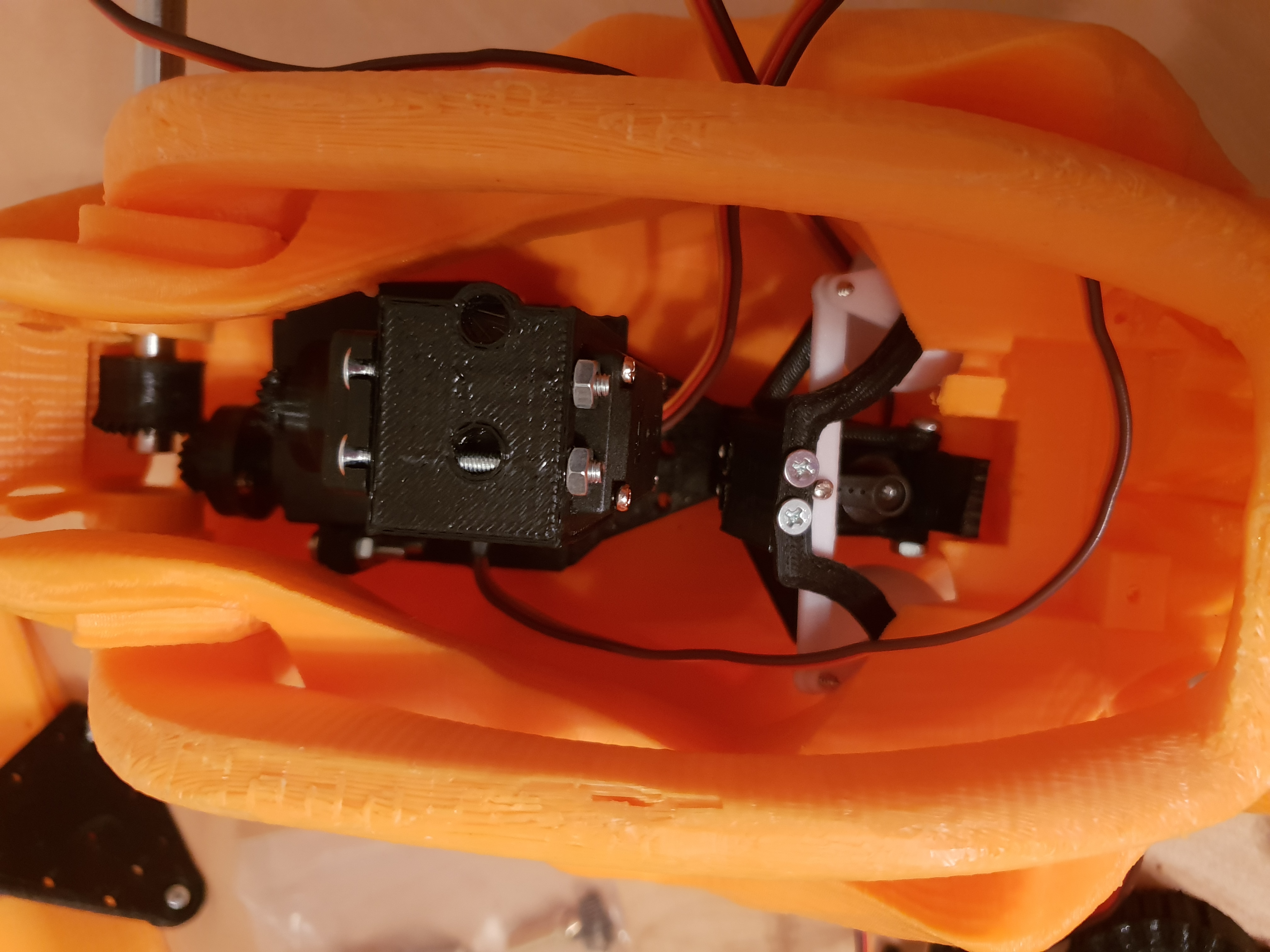
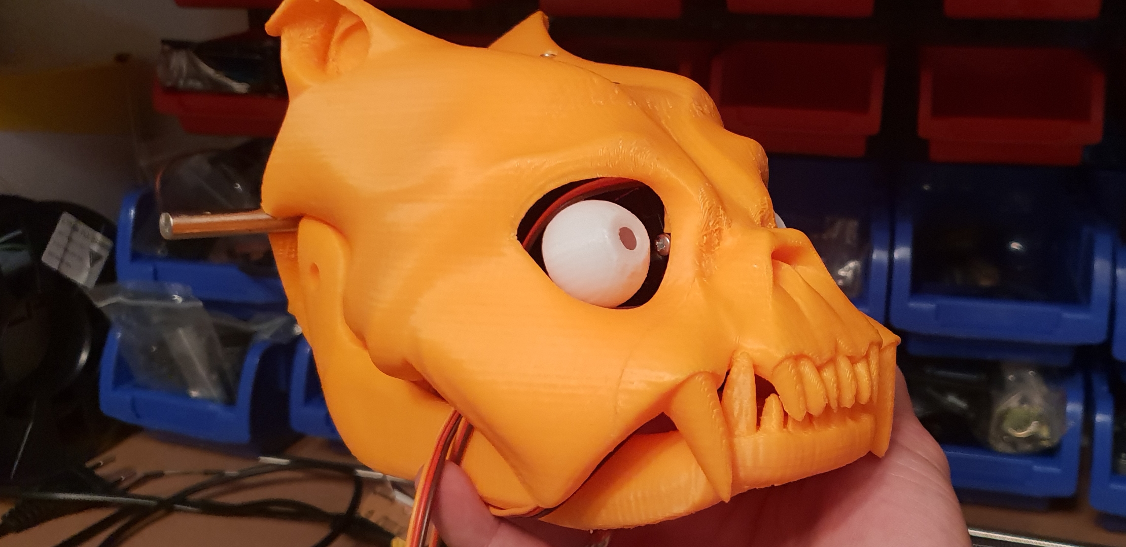
Some further troubleshooting and remodeling of the eye linkages later, and here´s the head all assembled and ready for testing.
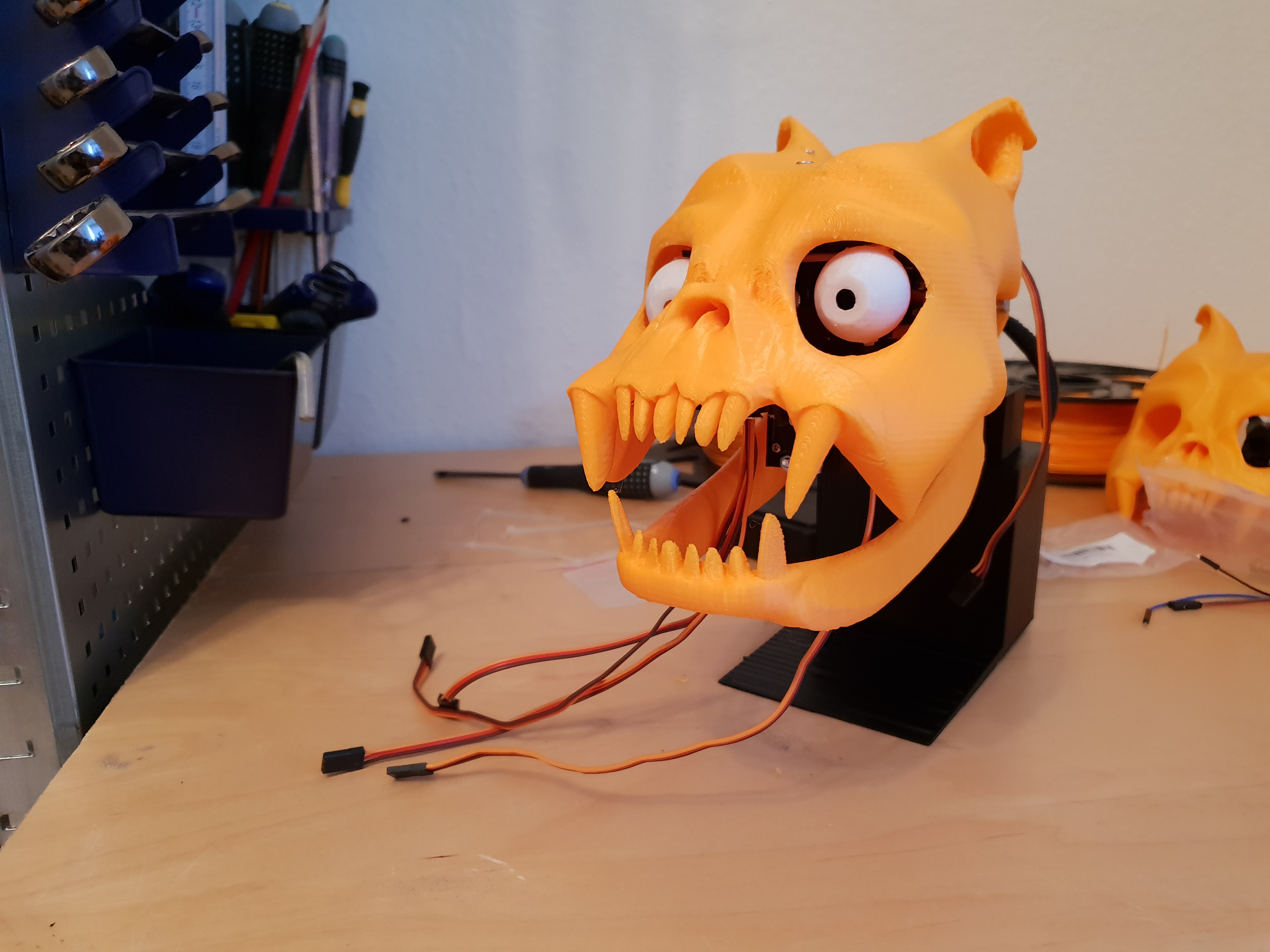
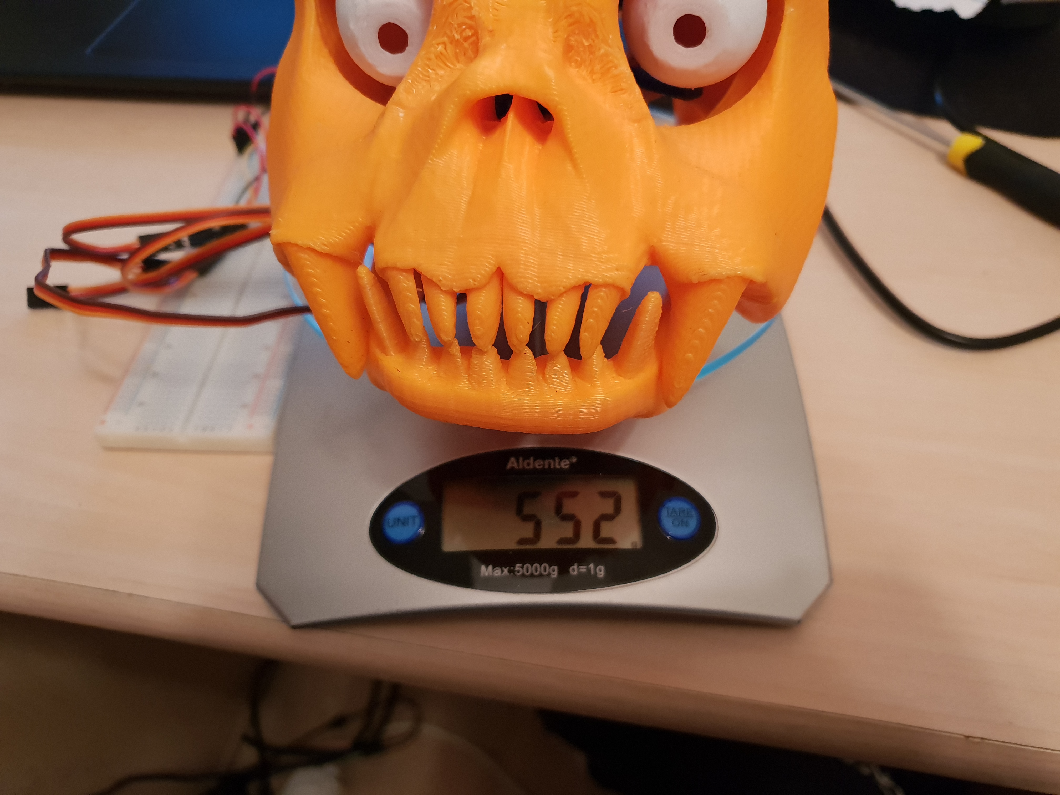
I mentioned my doubt about the strength of printed gears, and it turns out I was right. The head currently weighs in at about 550g, which is way too much for those small teeth to handle, as the video below will show. Also, I found the limit of the arduino´s amps supply, you can hear it tripping out just before stripping the gears.
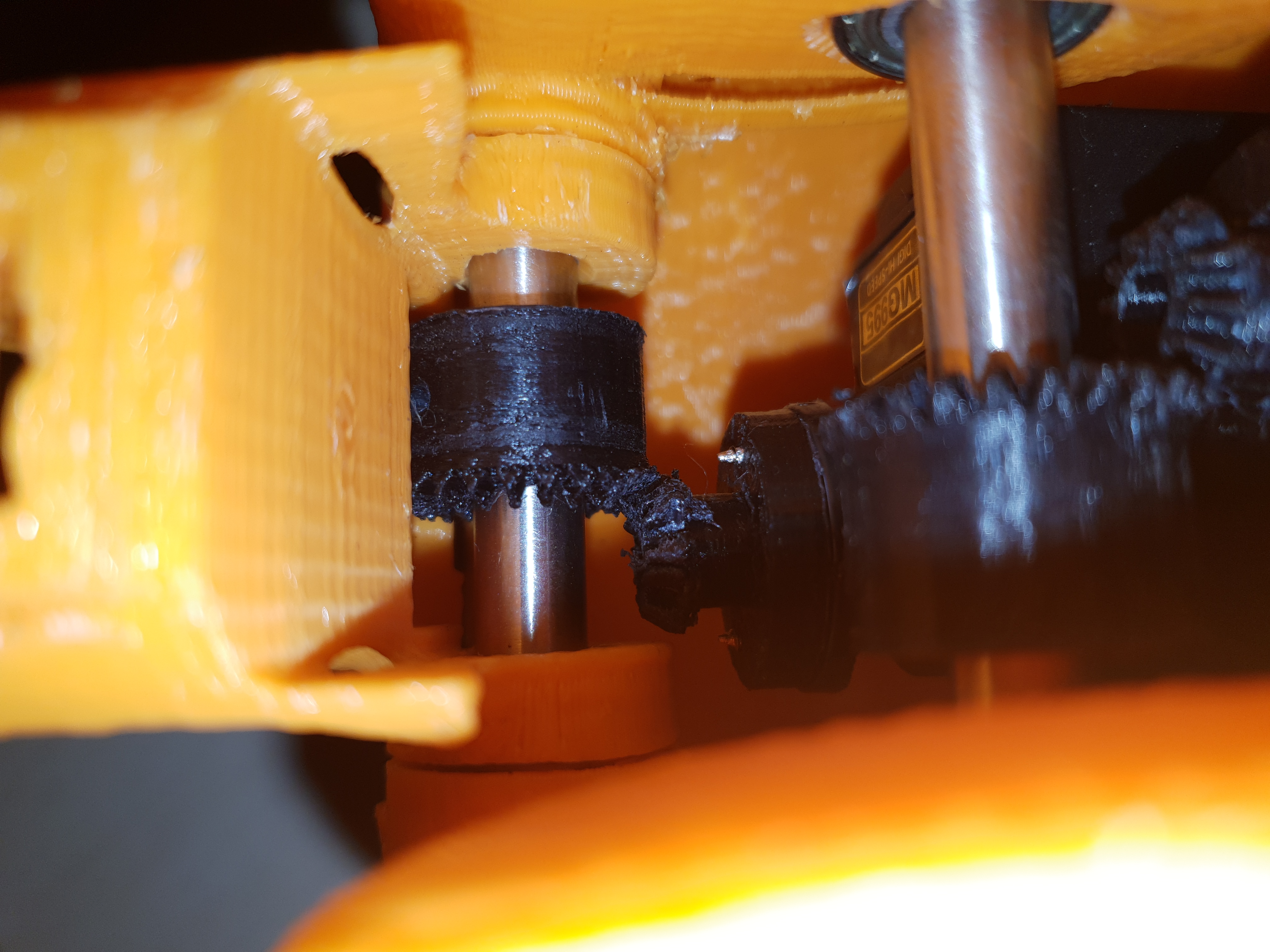
The carnage^
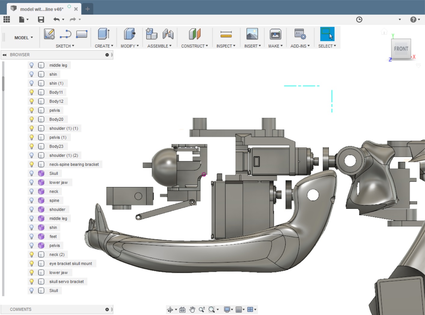
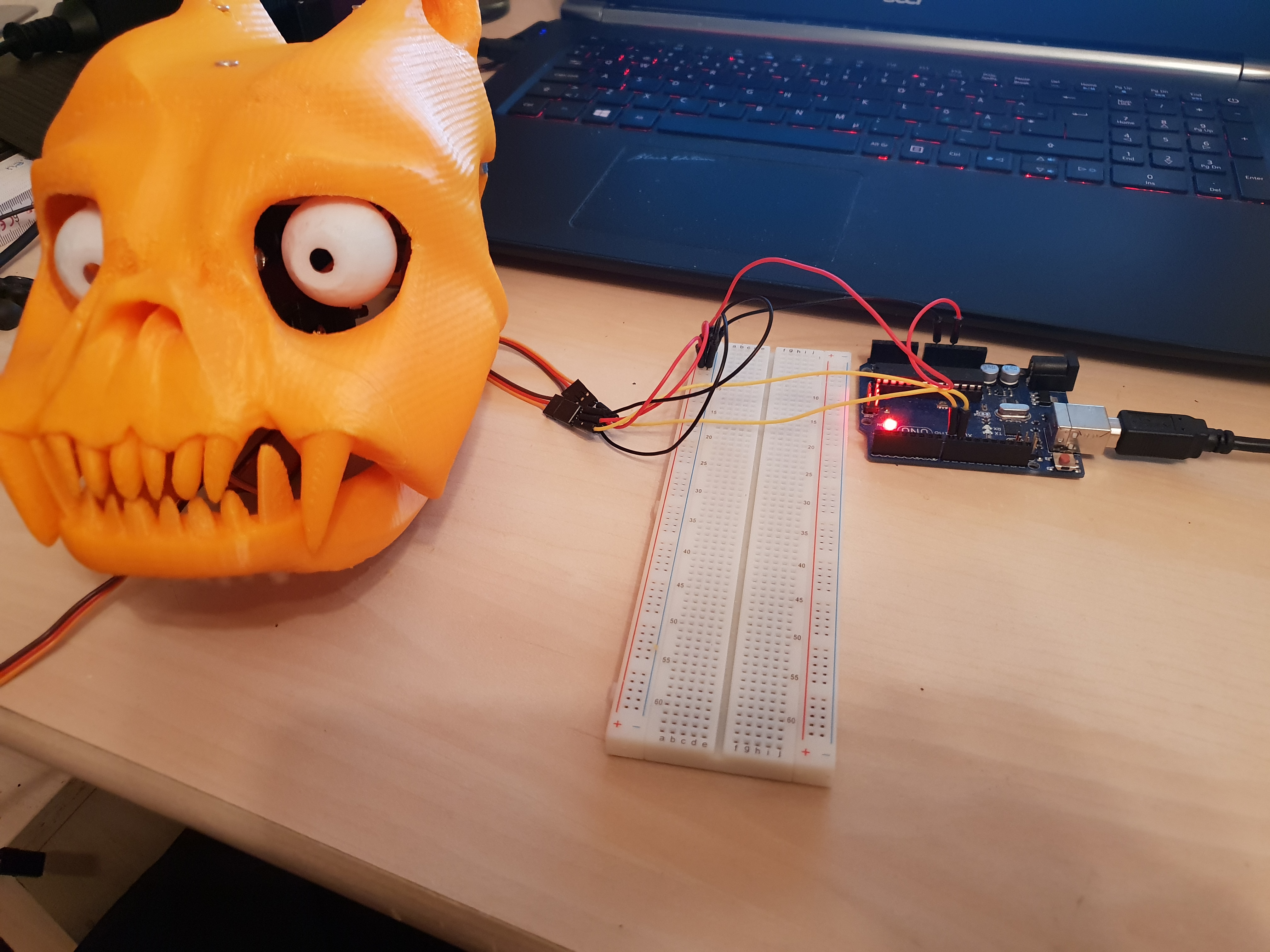
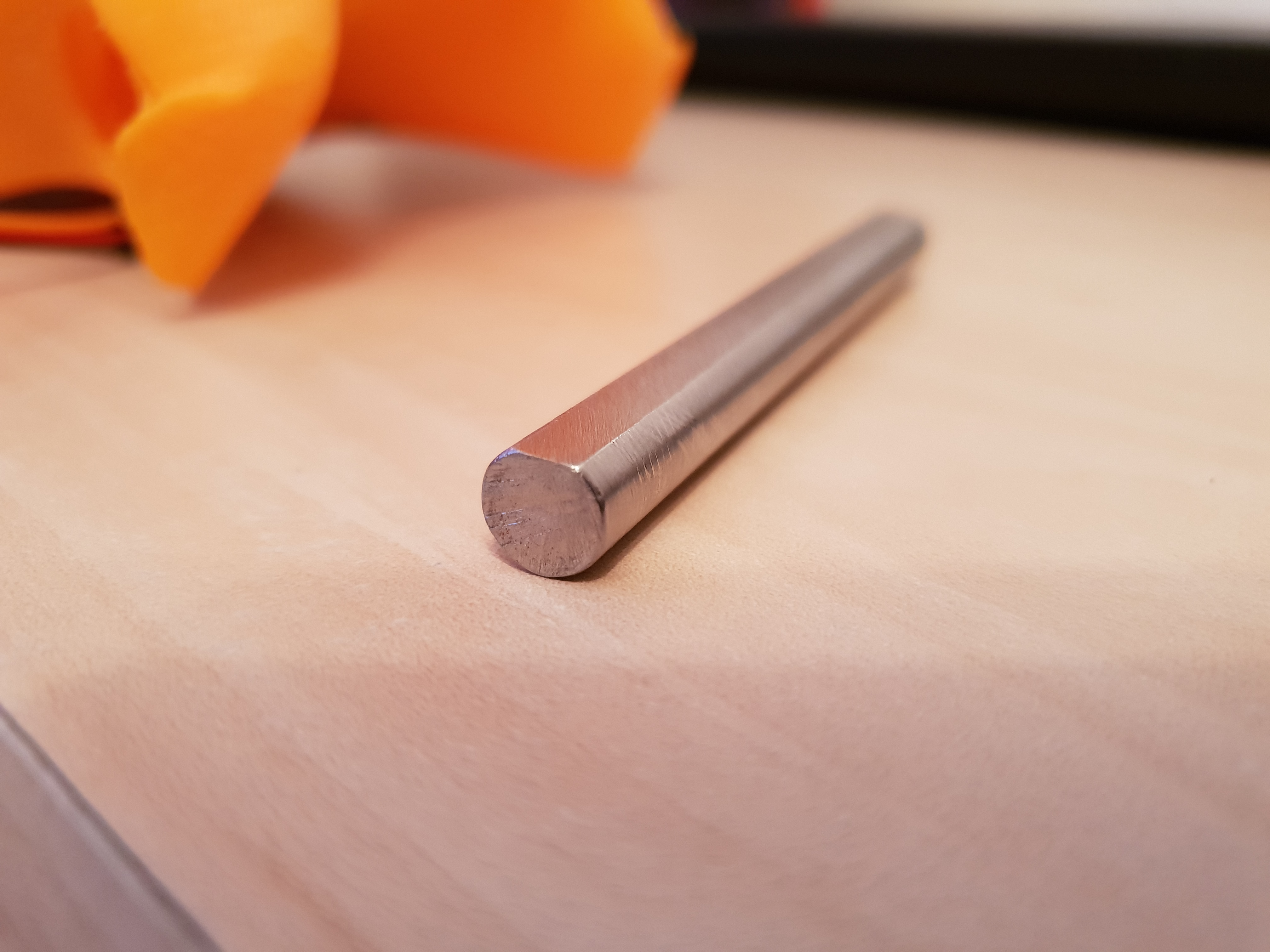
Good thing then that I had some metal gears already on the way. I also mentioned that I had ordered the wrong kind of servos, so it was pretty much as uncontrollable as it seems in the vids. I therefore ordered a new set of servos, making sure they were the 180 degree kind. I´ve slotted the axles as well for the steel gears setscrews, the plastic ones were a pressfit.
The next couple of videos show the jaw movement and the eyes in a testloop. The eyes still have limited movement due to the large radius around the vertical mounting bracket, I will remedy this at some point, either by shaving the skull or redoing the eye assy entirely, but this will have to wait till some later time as I am considering a delete of the bigger servos and instead going with dc motors for the neck and jaw, maybe also for the eyes. The servos take up at lot of space in there, that could become a problem when moving onto cameras and sensors.
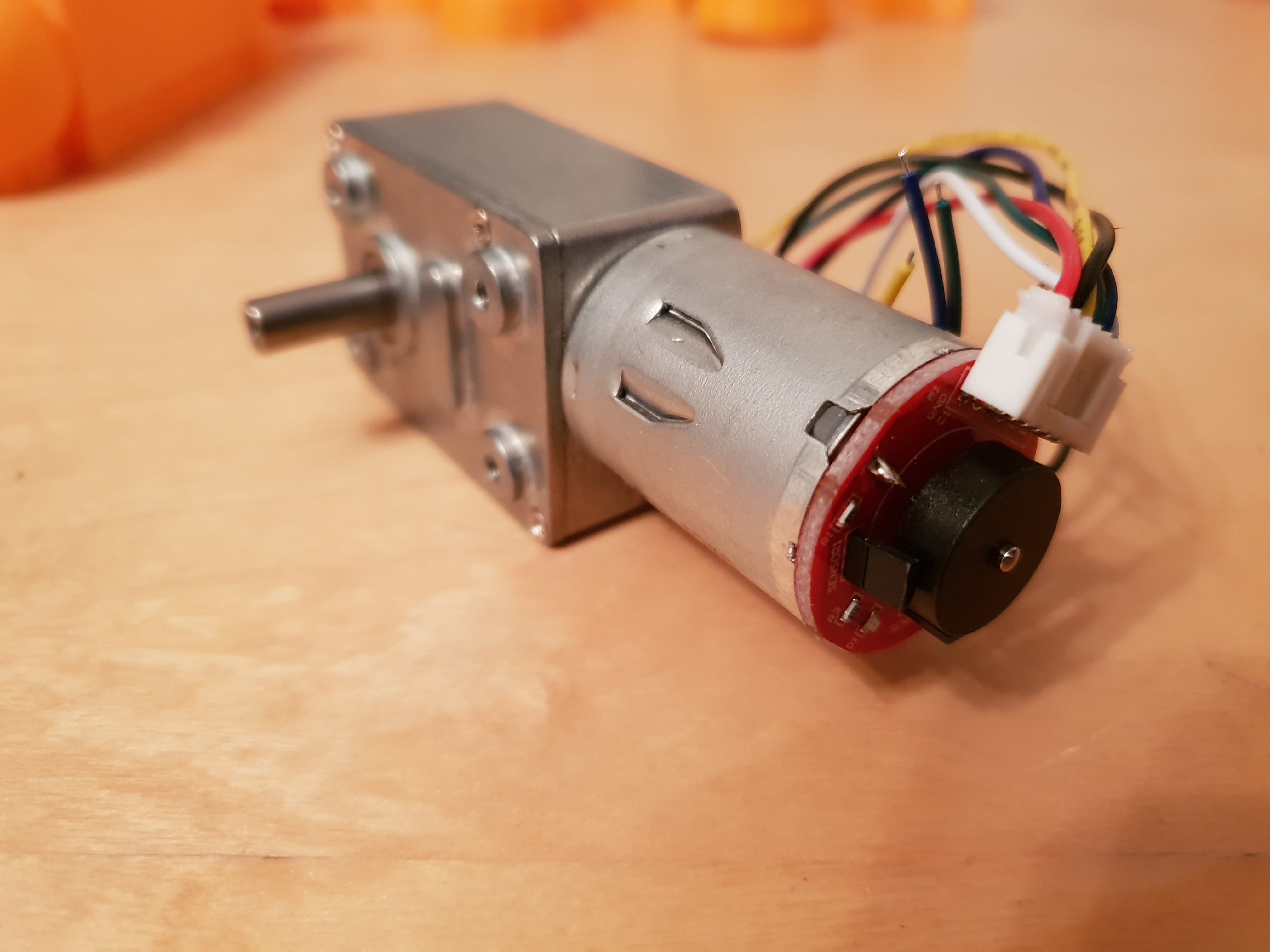
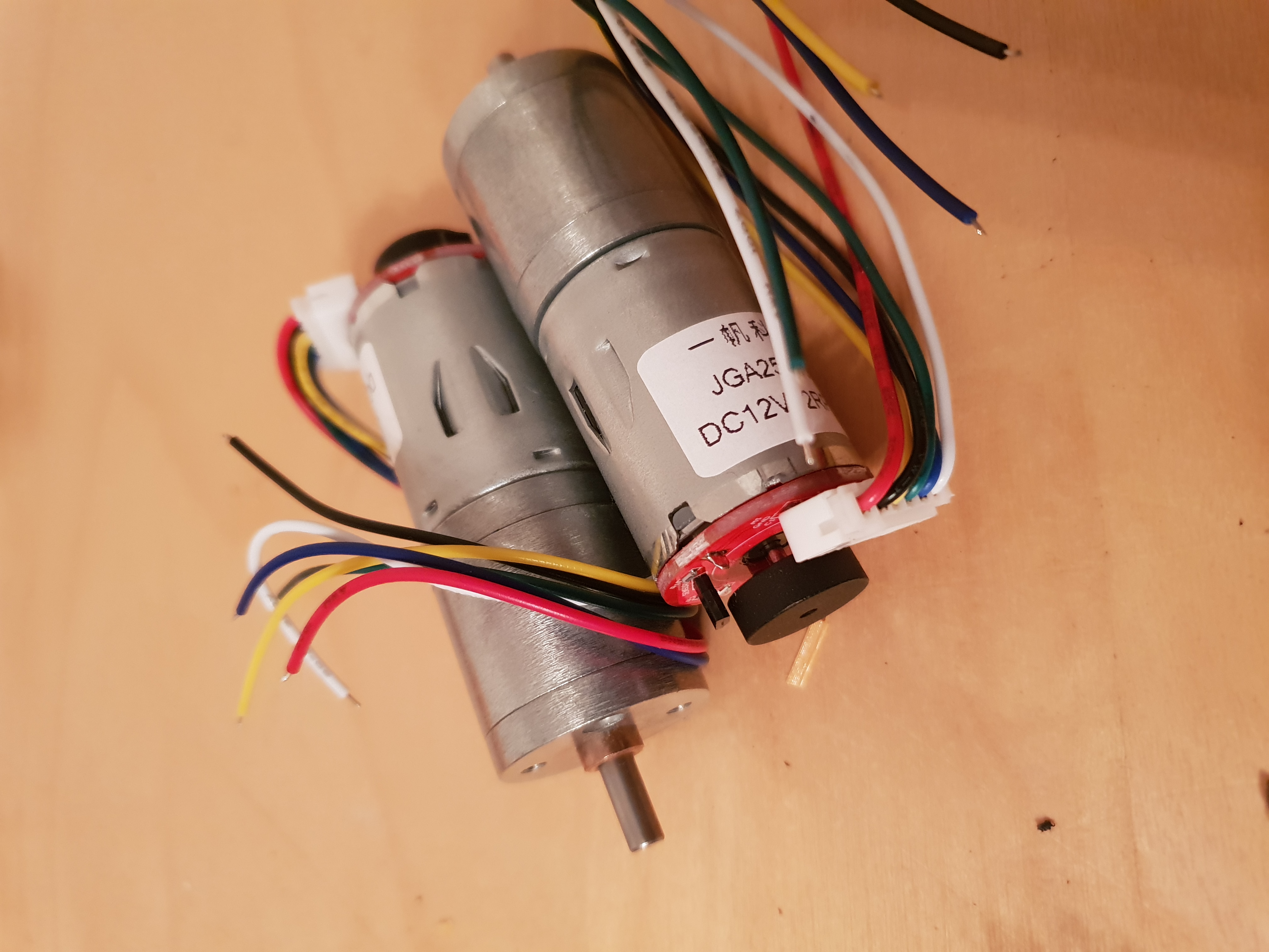
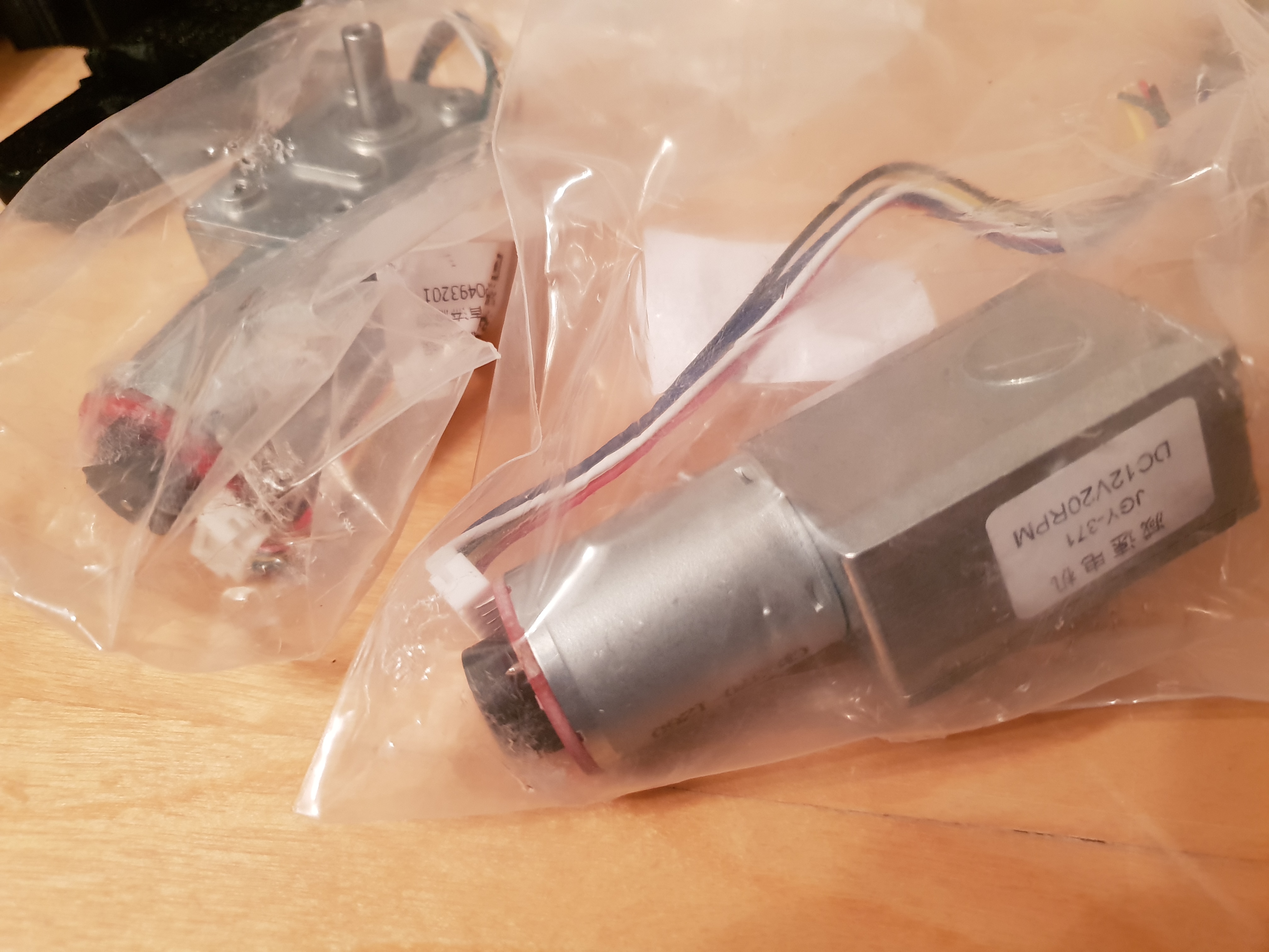
Anyway… Lots of parts have arrived, so I have finally been able to get the correct measurements, most of the sellers do include machine drawings in their products description, but i´ve come to learn that those are not always 100% true.
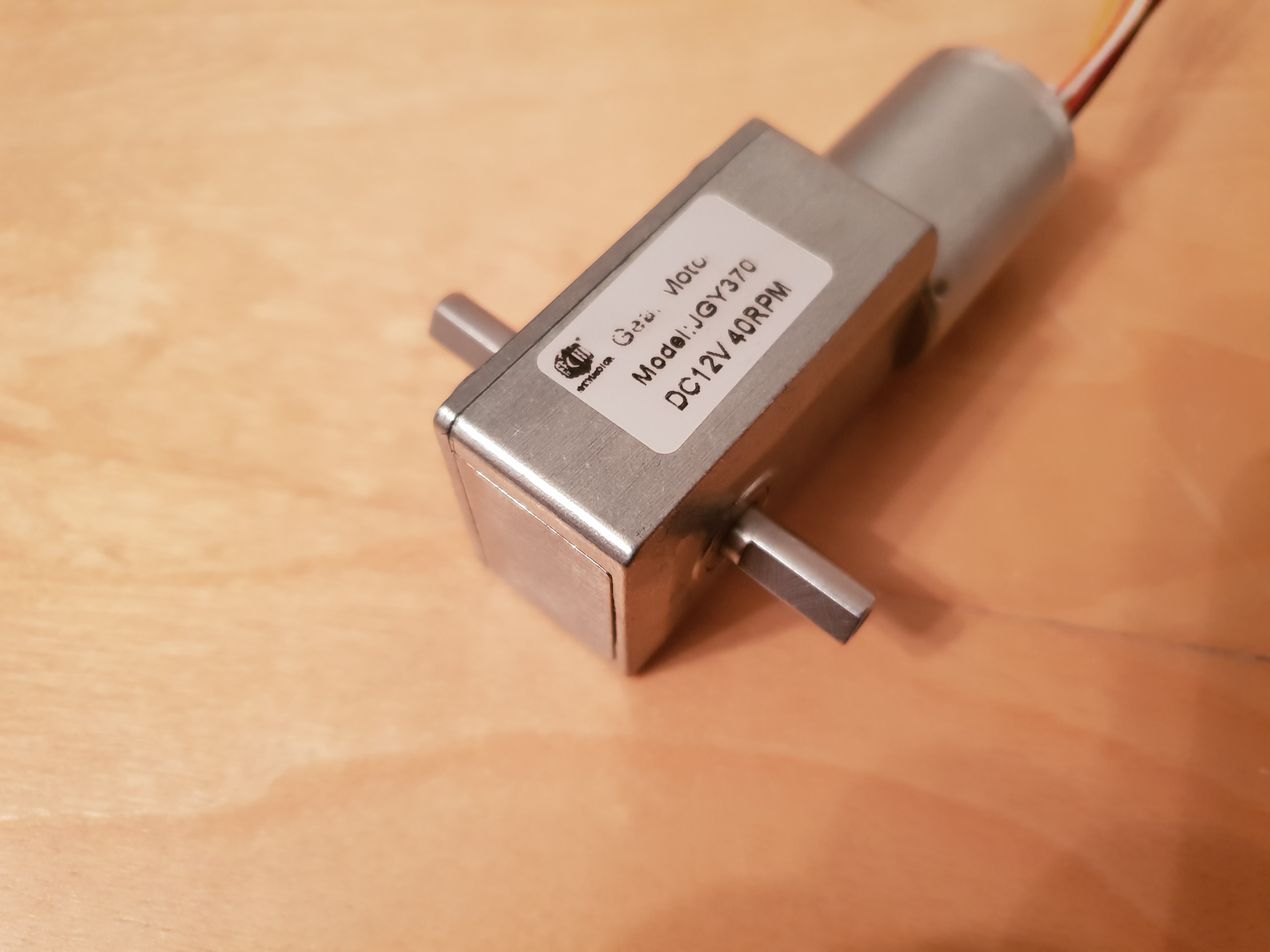
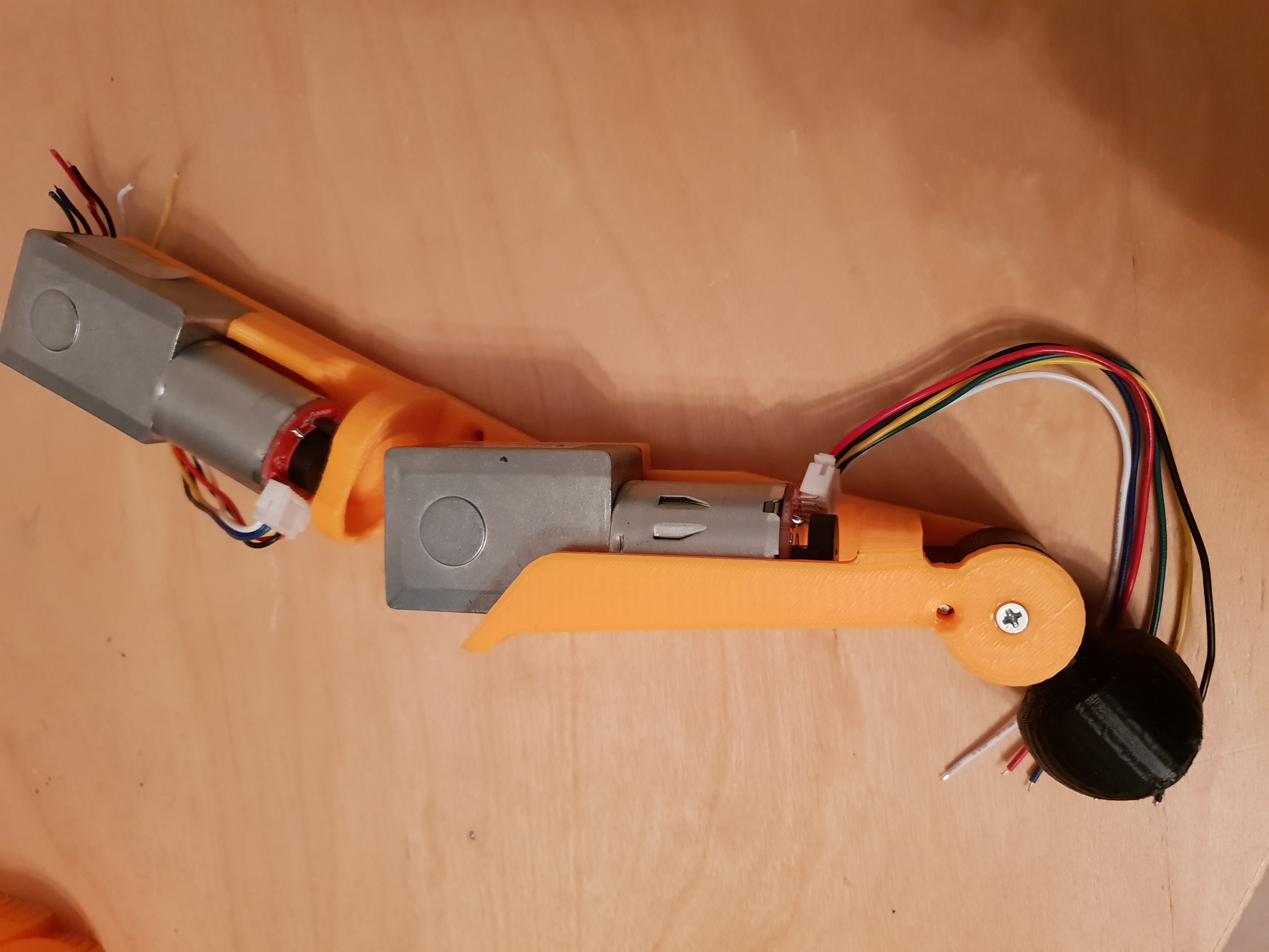
8x 90 degree gearmotors - 12v40rpm - for the legs
2x 90 degree gearmotors - 12v20rpm – one for the neck (horizontal) and one for parts (need the encoder for the double sided one)
1x double sided gearmotor – 12v40rpm - for the pelvis/spine joint
2x (have 4 more on the way) straight gearmotors – 12v12rpm – for the neck (vertical), jaw, shoulders and hip
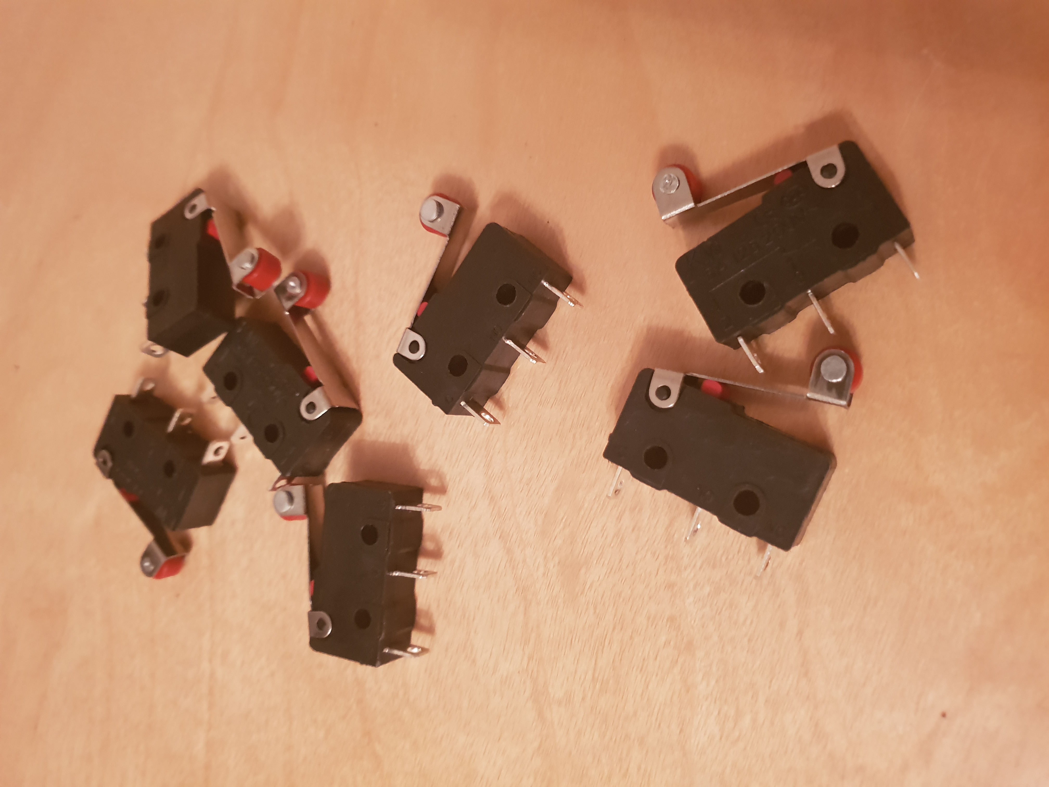
20 endstop switches
4 sets of gears
Pics:
So, moving on to the legs.
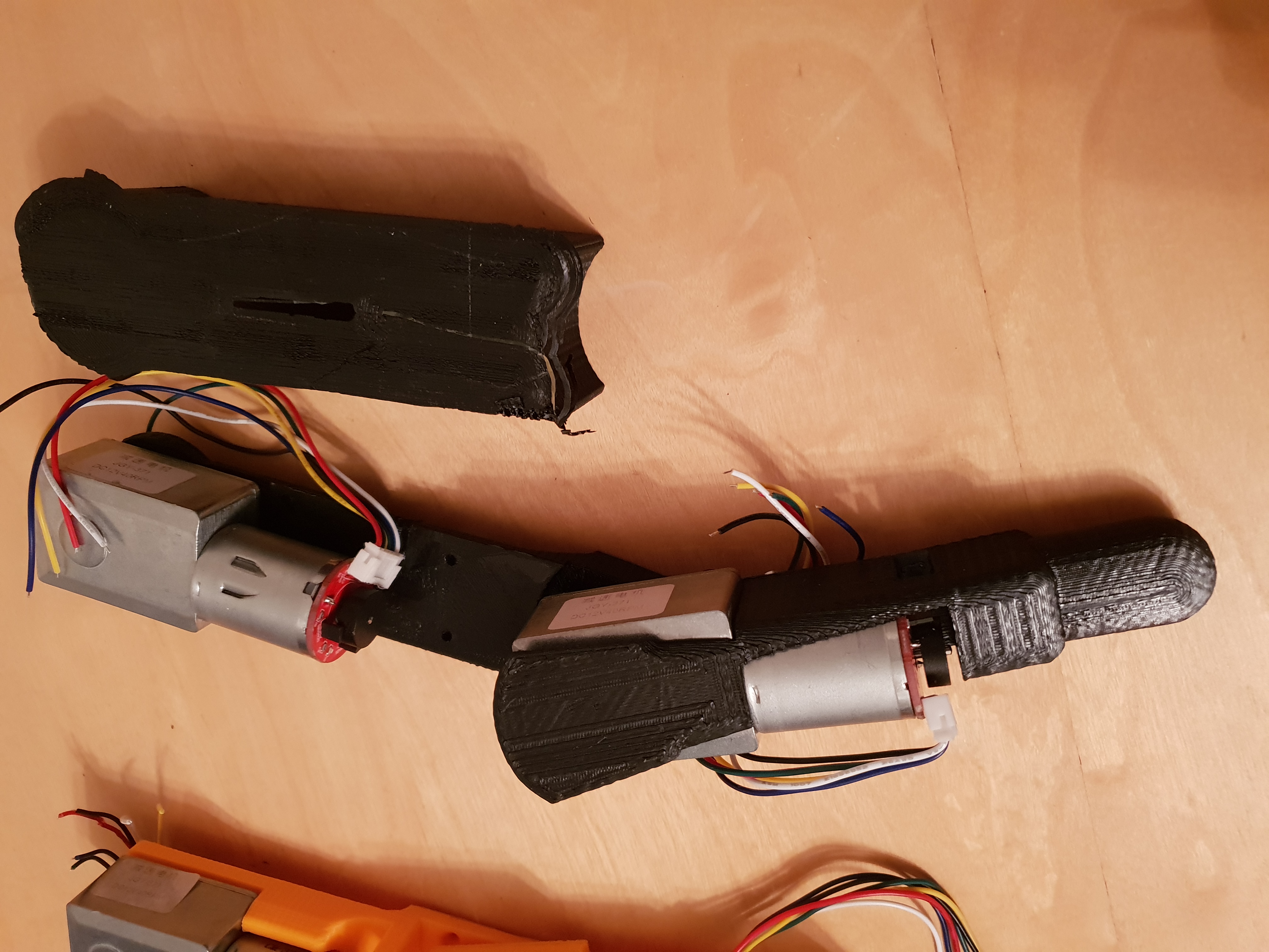
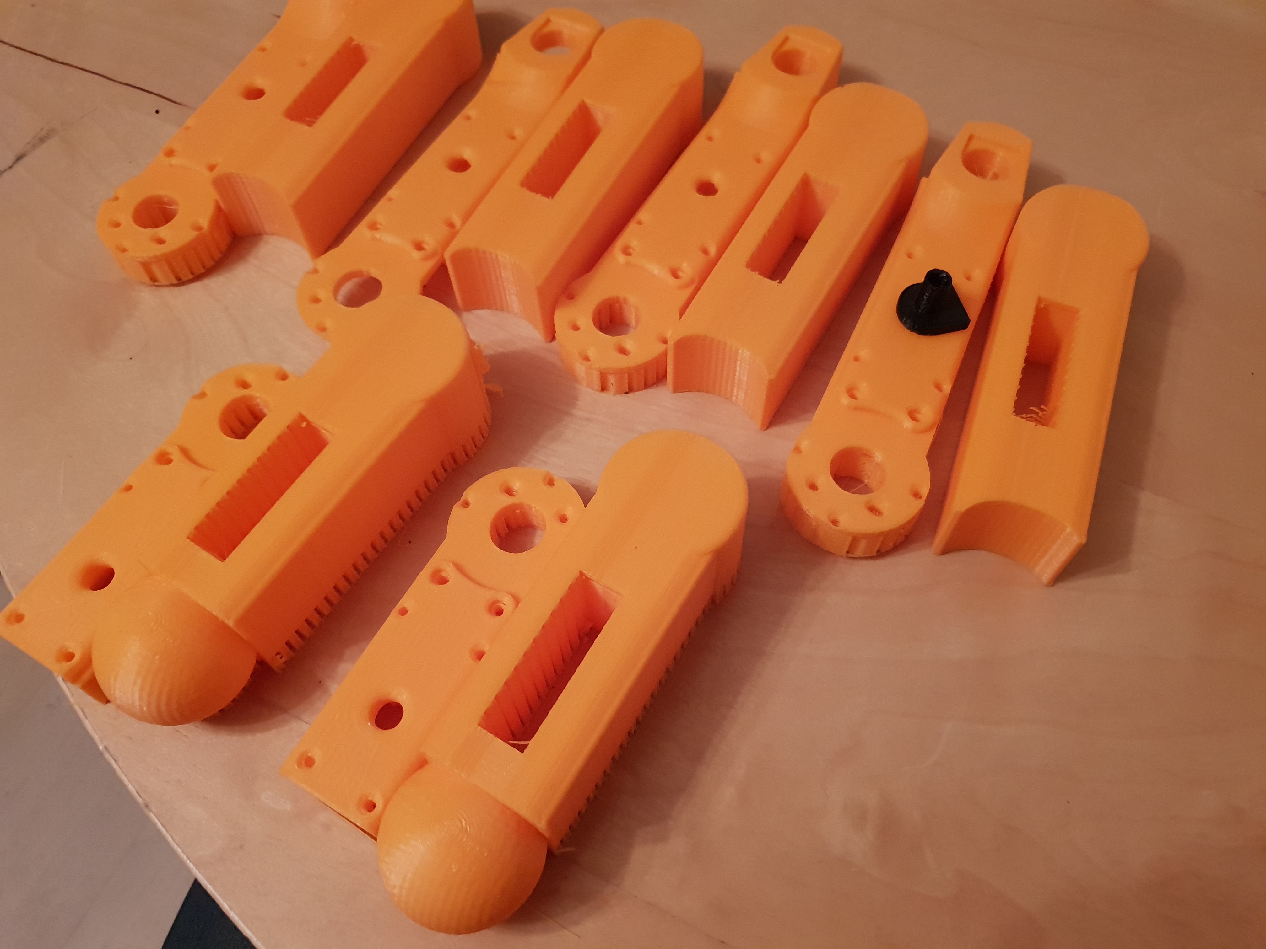
I had already done a couple of versions of these, but I decided to start over again as I just wasn’t happy with the way they looked. 3-4 designs later and this is what we´ve got.

One with, and one without suspension. The thought behind the suspension is to relieve strain from the joints on impact movements (jumping, etc). But really this looks horrible, so back to drawing it is.
I made a couple of different designs, trying to slim the legs but they just ended up too flimsy or with not enough room for stuff like screws, bearings, switches and so on.
This was a real pain as I really want the robot to look right, like an actual bone structure, and I finally accepted that it just isn’t possible with the motors I have, and gave up on them.
So this is the final version, a bit bulky but pretty enough that my eyes won´t bleed out every time I look at the thing.
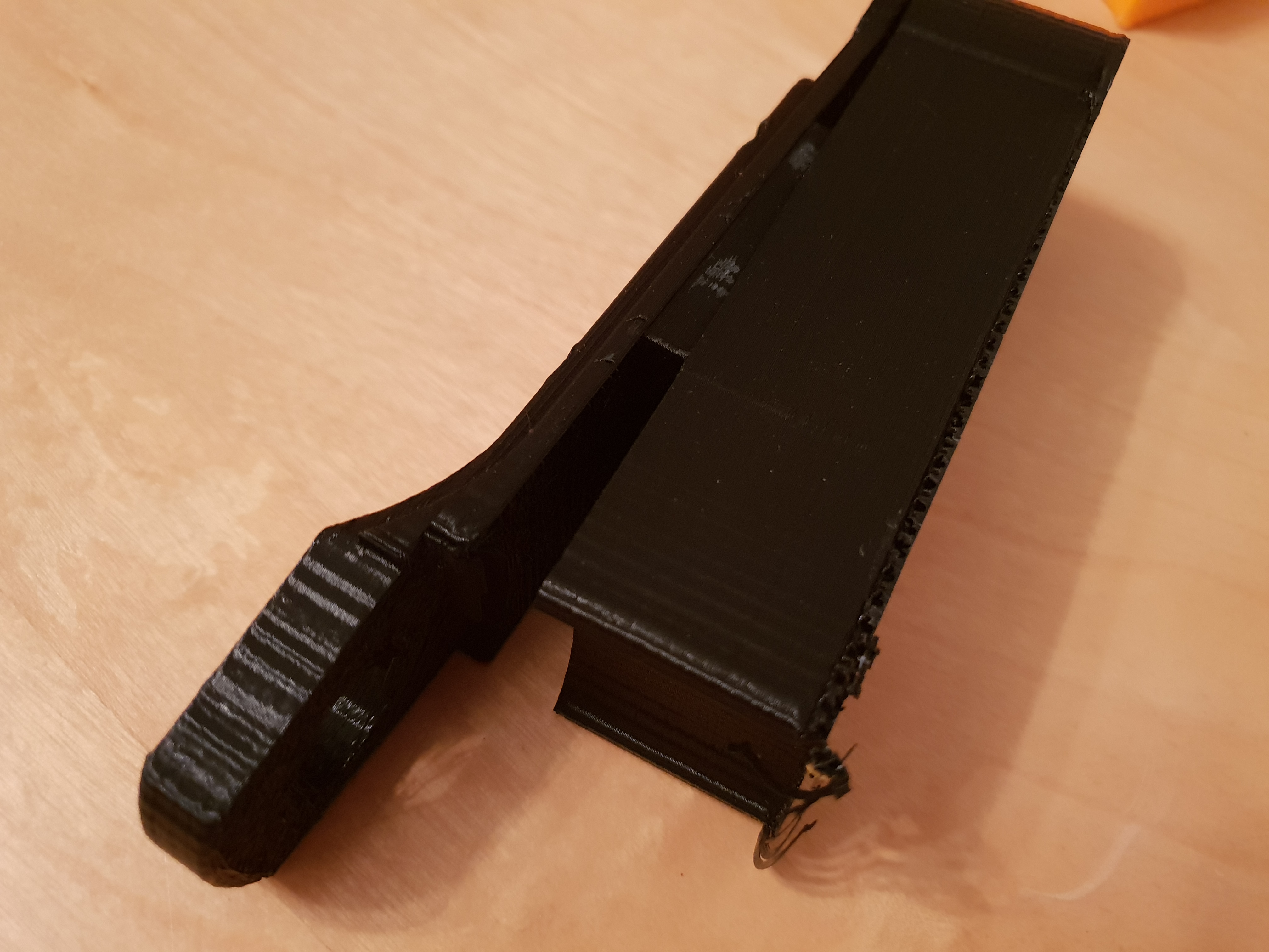
A testprint of the uppers.^
I have been studying other smaller robots to get some inspiration, and I thought to instead going with smaller geared motor assemblys, kinda like Sony´s Aibo, or a set of actuators. The smaller motors though will probably not be able to supply adequate torque further on, so I think im going with actuators. Ive searched far and wide for some that has a small enough form factor, at a reasonable price, and I did find a few candidates. Unfortunately they don’t seem to be fast enough when they get smaller, so I guess i´ll have to cook something up myself once I decide to move on with the idea.
Doing it this way may actually be the best solution afterall, i can then arrange the rods and linkages to better resemble the bones of a dogs leg.
Right now I just want to get the legs and shoulders done so I can get the joints and motorbrackets situated, and the spine finished, I´ve finished modelling the pelvis and shoulders also, so really I “just” need to model in some brackets for gears and motors. When I say “just”, I mean it will probably take the better part of a week to do, my printer is not the most accurate so I does sometimes take a few testprints to get the tolerances right. For example, one set (2) of the upper legs take 15 hours to print, and i´ve had to do 5 in total of those before everything fitted correctly, so… PATIENCE, is the word.
Shoulder and pelvis pic^
The last parts the legs are printing as im writing this.
..
I took a break from the project over the christmas holidays. I needed to step back a for bit as I was getting somewhat frustrated with the leg assemblys. Ofcourse good enough is not good enough, knowing myself I should have realized this earlier.
So, I had a re-think and after testing some stuff in my head I decided to bin my previous model as it had a few issues. Having the motors attached directly onto the legs would require a lot of torque from the motors, drawing high amperage given the amount of weight hanging about during movements. This would most likely also give me a hard time when trying to create a balancing program. Idealy, as much weight as possible should be centered, the more weight I have situated in the periphery, the more I will be limiting the robot in its movement and having it fall over all the time.
Another problem arises when making the joints, my former models all had the bearings situated to one side, meaning that the whole structure is resting unevenly on the joints, making them twist and applying lots of force on the gearbox shafts, this could result in failure of the shaft bushings.
Gears, rods, levers and such would make for a very complicated build, again with unnecessary weight, so I have made my final (LOL) decision, and I am going with cables. I did think about this solution a while back, but at the time it seemed too complicated.
I have an old motorcycle which I am rebuilding and doing extensive modifications to, and when I was test fitting the grips and handlebars it dawned on me how simple it could be done.
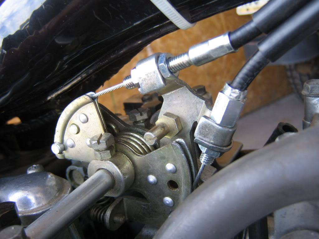
The throttle has 2 cables connected; one for opening and one for closing, opposing each other’s directions on the same pulley, surely this principle could be applied on the robot as well.
So I did a mockup, and YES it works
I can now have all the motors inboard, bearings can be centered in the joints and all I really need in the legs is a few mounting points for the cables and routing holes for cable sleeves. Apart for the joints themselves I can then model it any way I like, without having to make room for hardware.(I will need some switches, but that’s no problem)
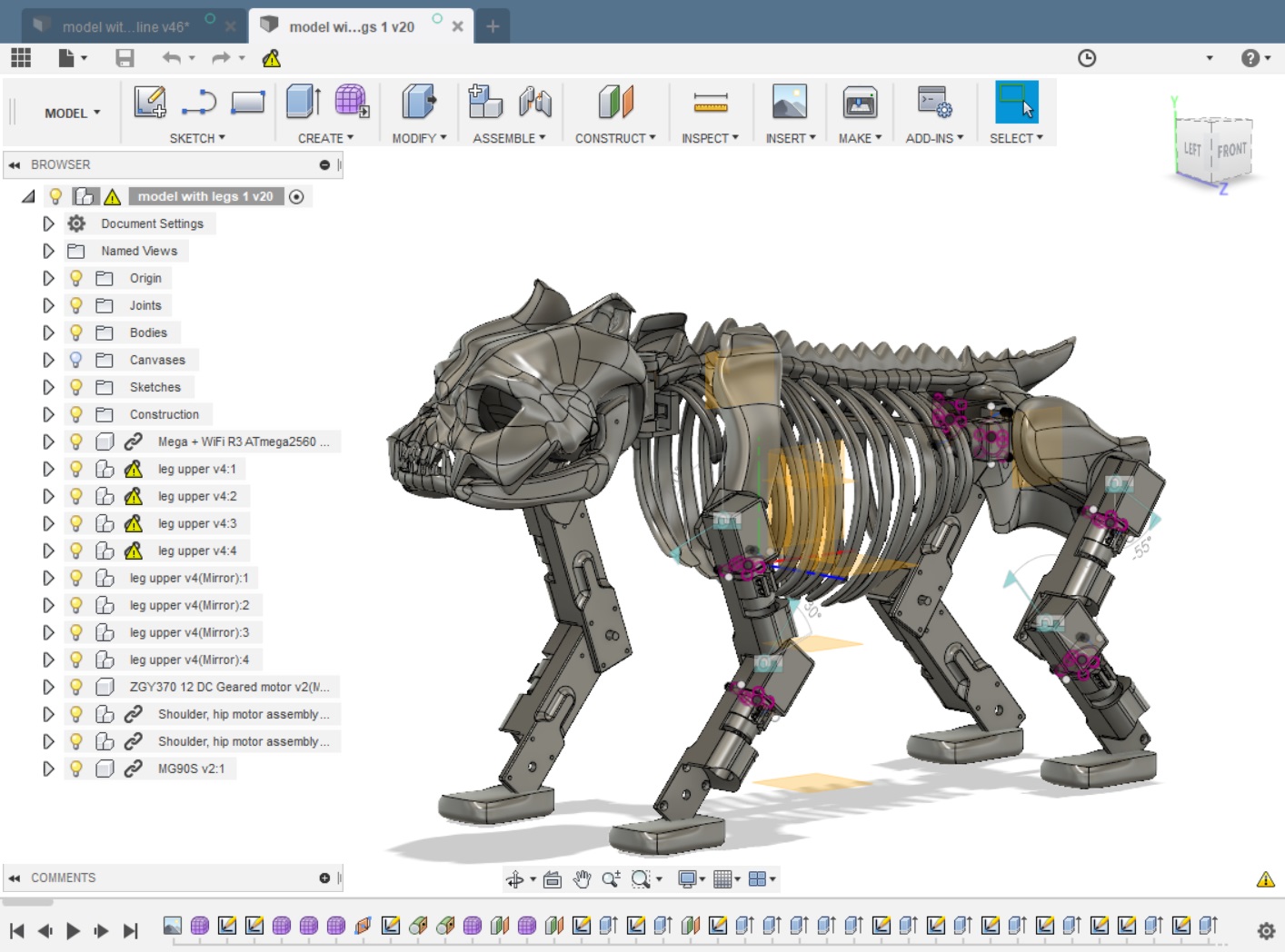
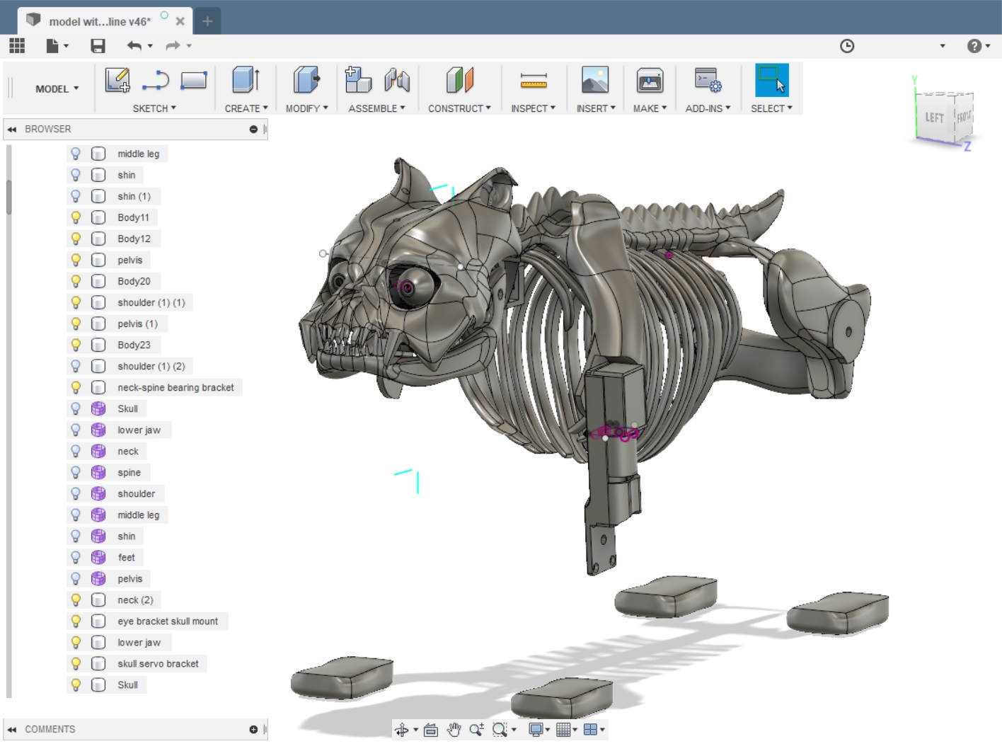
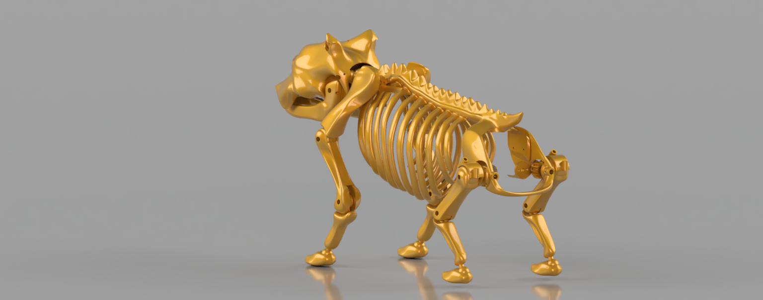
Model model model, and here we are! Finally something that actually looks like a bone structure.
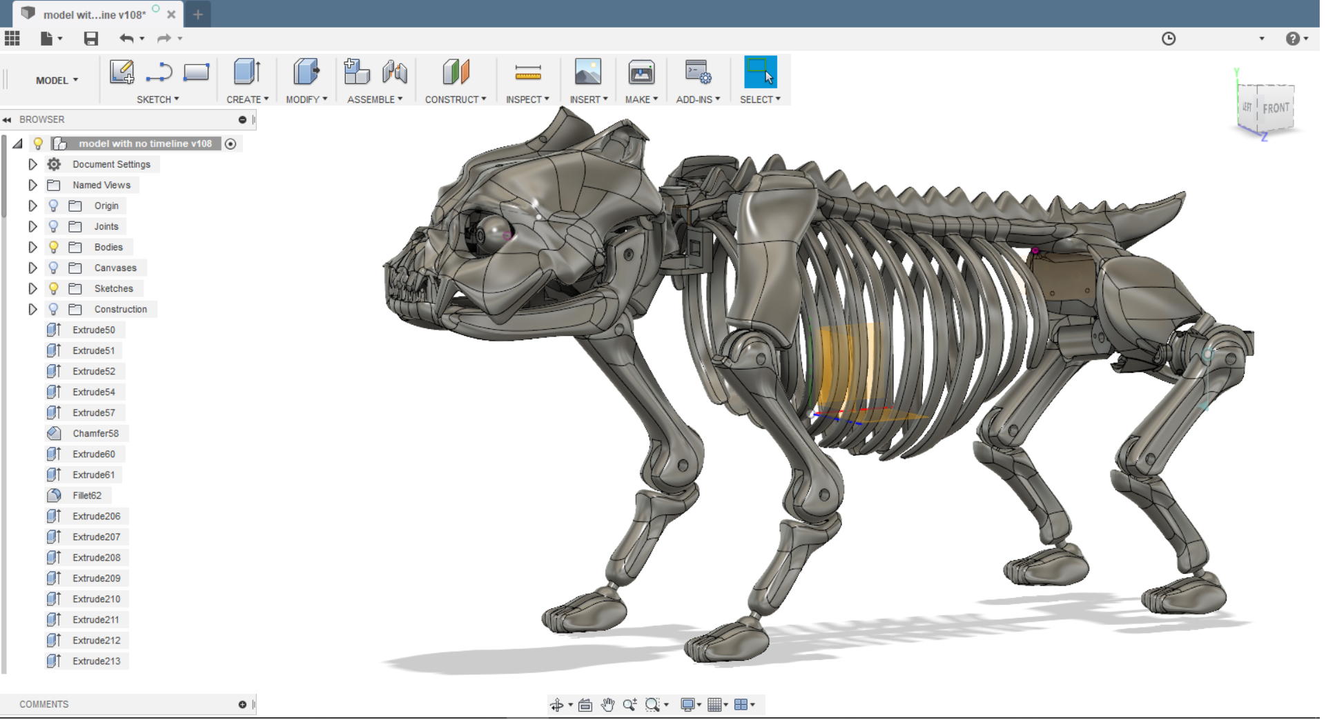
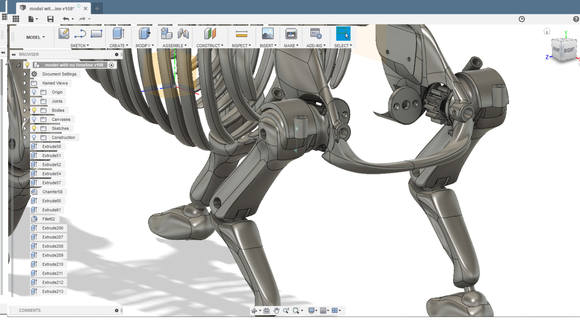
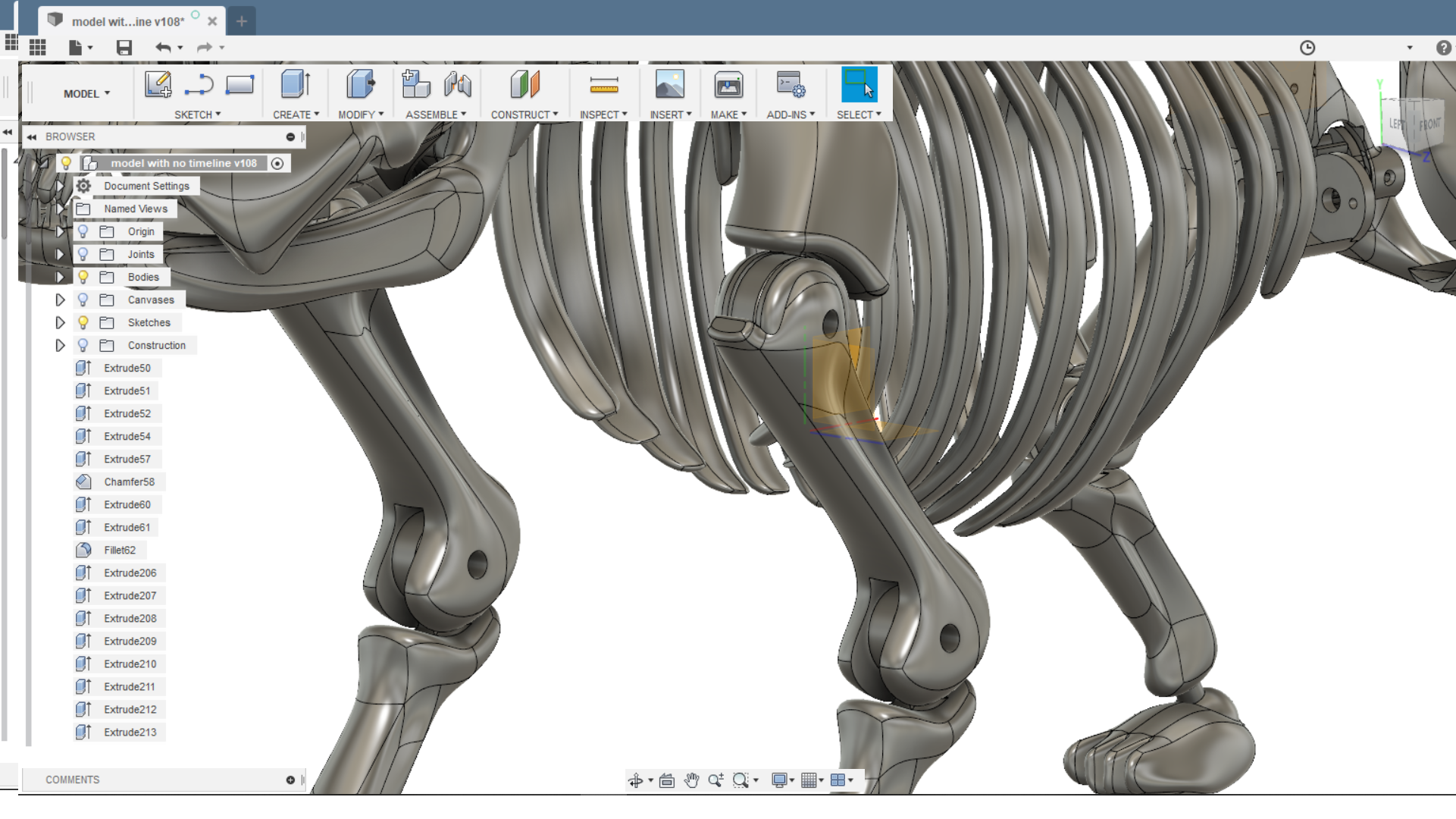
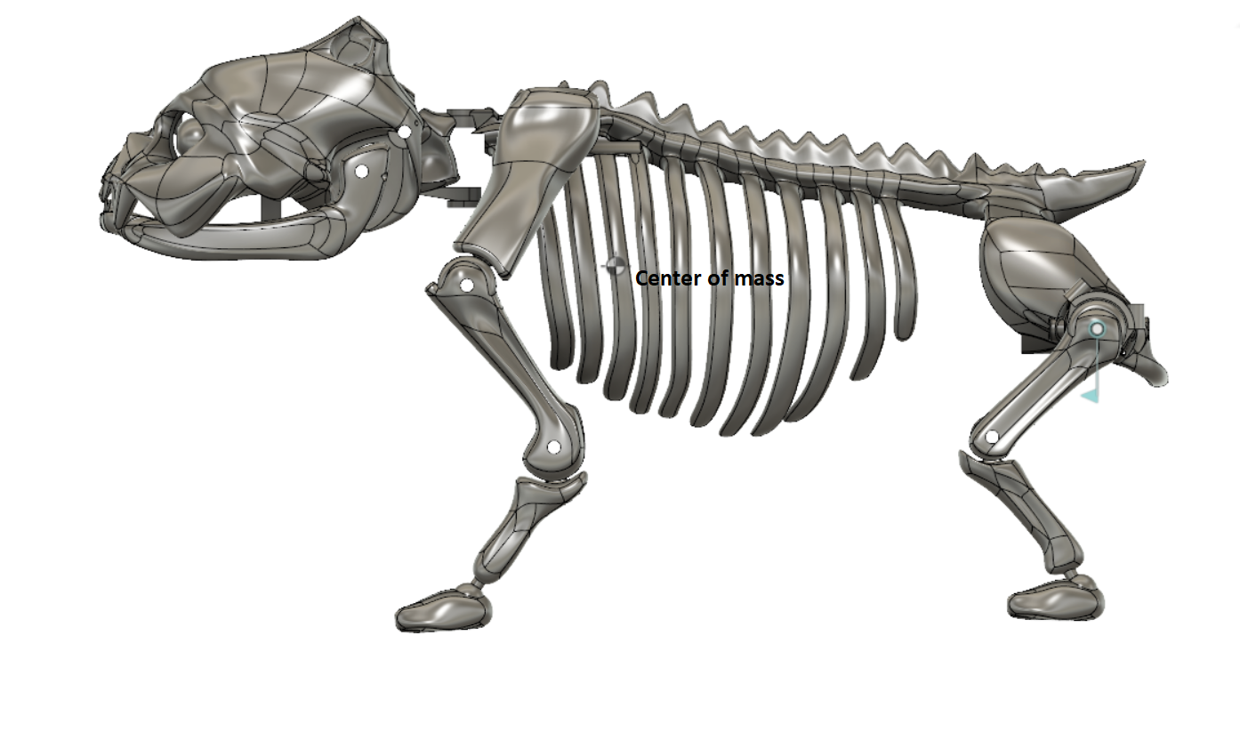
Also-
Fusion has the ability to calculate center of mass, and I lucked out it seems. The model itself has its center of mass right behind the shoulder blades, when I ad in the motors it will move backwards and down a little bit, giving me a near perfect result in the end. I was quite stoked about this when I first saw it.
All I need now is parts (cables, sleeves, end plugs, antislip pads for the feet, springs etc. etc.), everything has been ordered and is on its way, unfortunately my local postal service has managed the lose the cable sleeves last week, so I’ll have to wait a bit longer for those. Luckily their dimensions are not critical so it’s not going to affect me too much, it’s just annoying.
Once I have modeled in some mounting spots for switches, everything will be ready for printing. I actually need to have the skeleton assembled in order to do testing for motor mounts and the drivetrain I general.
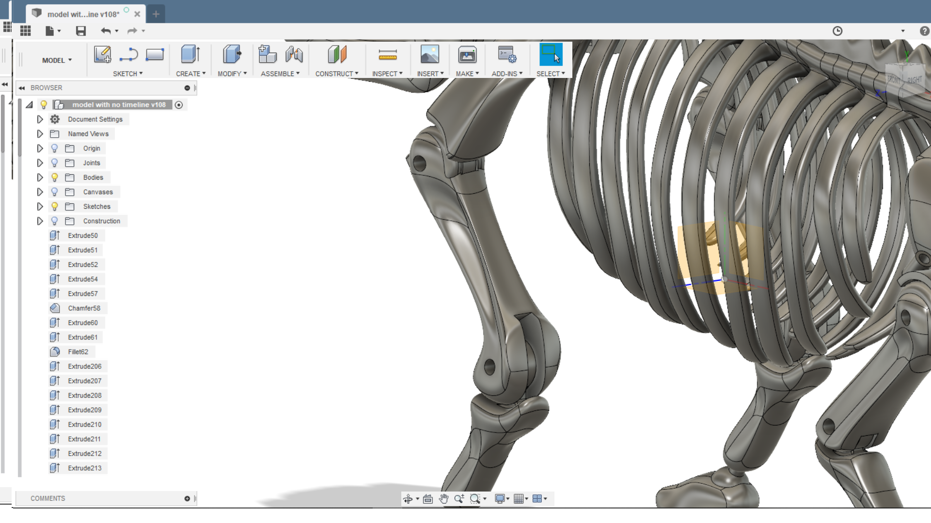
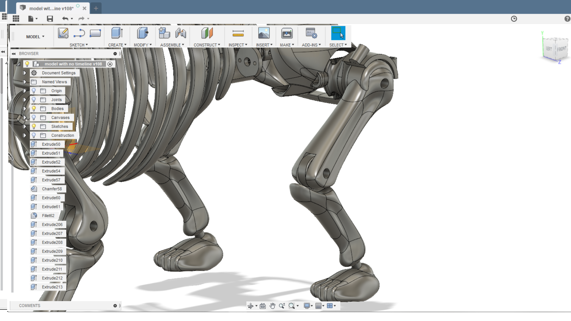
It won’t be long now, and I am so excited to see it built for the first time, in the meantime here’s some renderings to look at:
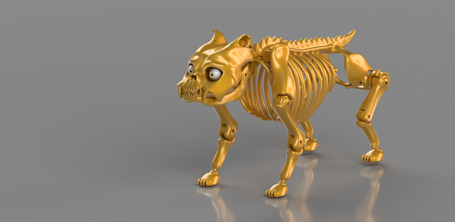

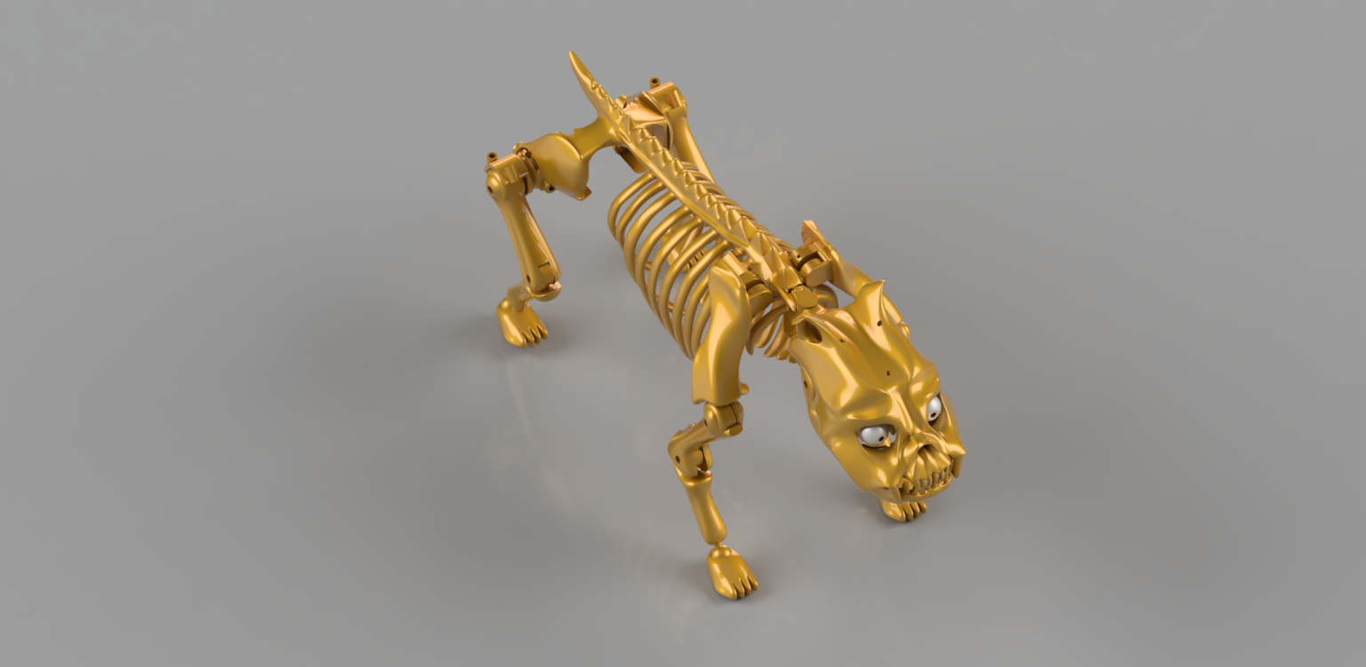
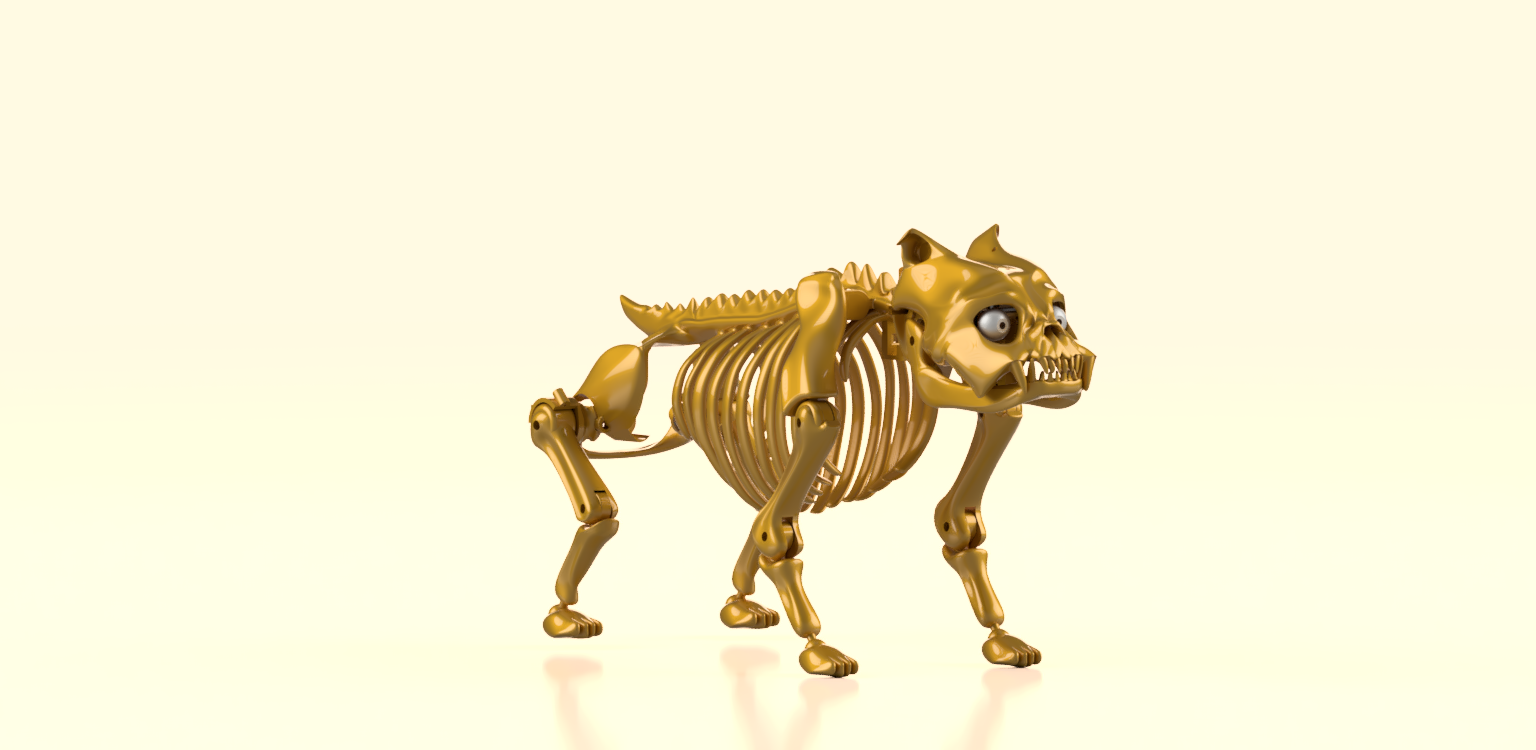
^these are not 100% accurate as theyre rendered in perspective view, i did set it to ortographic but for reasons unknown to me theyre not.. whatever though ;)
Now it’s coming together I think the head looks a bit slim tbh. So I will stretch it a bit wider and higher, I need to reprint it anyway as I am replacing the servos with motors, and changing the mechanism for the eyes. Not sure if this will have priority, so it may be a month or 2 before I make these changes, or maybe I’ll do it tomorrow, idk xD.
Also I will redo the neck joint, as this servo is getting replaced with a cable drive as well, and likewise I will create a joint for the tail to wag about.