


Simple Line Follower
Hey guys I recently found all my documentation for an old line follower we had to do for a first year course at my university. We did these in teams of 4. I built all the hardware and did a majority of the electrical. One other group member did the coding and one more did a CAD rendition of the prototype I built. The goal was basically to complete the track as fast as possible. Obstacles included size requirements, paths to chose from, breaks in the path, a block that needed to be pushed into a trench and not falling off the table. Our team was the 4th fastest out of about 20 Arduino teams and 20 LEGO NX teams.
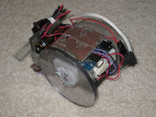
We were given all the electrical parts/suggested diagrams. As far as I can tell parts where sourced from robotshop, digikey and solarbotics. I got hold of Lexan plastic and spent two days after lectures in the shop just eyeballing and cutting. The arduino shield was done in a similar sloppy fashion with no prior layout planned (I have no pictures of the shield so please don't ask me).
Just kinda winging it with Lexan and 2 part epoxy....
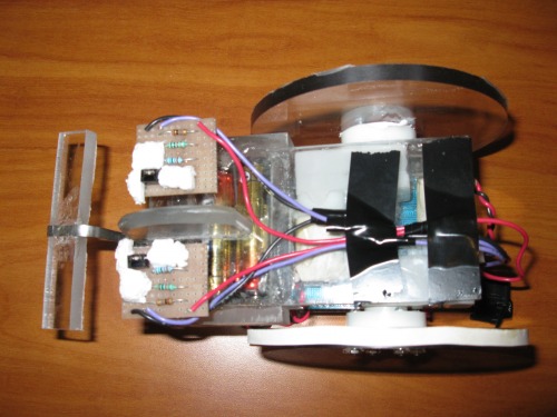
Bottom View
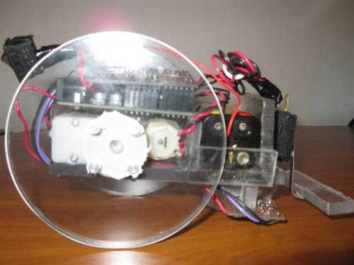
Side View
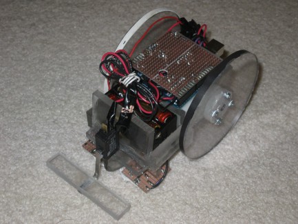
Rear Isometric View 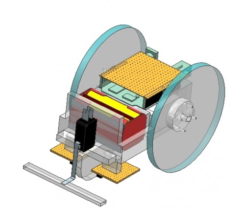
Front Isometric CAD 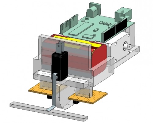
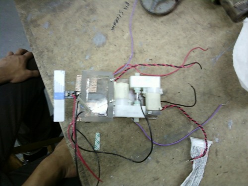
Same view with wheels and shield removed. 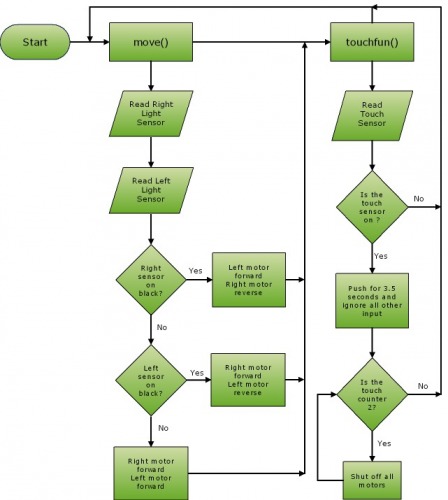
Here is an explanation of the program that I made as part of our write-up. Move() is just drive forward and Touchfun() is just a function that monitors if the front bumper has been pushed.
Here is the code as it ran in the competition I had to clean it up because many last minute changes were made it it just before competition. It can be downloaded above as a .txt file.
//define pins
#define light1 5
#define light2 4
#define touch 8
#define PWM12 5
#define PWM11 6
#define PWM21 9
#define PWM22 10
const int blackl= 550;
const int blackr= 500;
//initiate touch counter
int counttouch = 0;
int lastbutstate = 0;
void setup()
{
//Set up pin output/ input
pinMode(18, INPUT);
pinMode(19, INPUT);
pinMode(touch, INPUT);
pinMode(PWM12, OUTPUT);
pinMode(PWM11, OUTPUT);
pinMode(PWM22, OUTPUT);
pinMode(PWM21, OUTPUT);
//one side of the motor driver output to low
digitalWrite(PWM11, LOW);
digitalWrite(PWM21, LOW);
//set up connection speed
Serial.begin(9600);
}
void move()
{
//set speeds of whiles
int full = 240;
int slow = 0;
//light sensors variables and constants
long lightsenl;
long lightsenr;
//read light sensors
lightsenl = analogRead(light2);
lightsenr = analogRead(light1);
Serial.println(lightsenl);
//if the right light sensor read black
//if the left light sensor reads black
if(blackr<lightsenr)
{
//turn right wheel back wards and left wheel forward
analogWrite(PWM21,LOW);
analogWrite(PWM22,full);
analogWrite(PWM12,LOW);
analogWrite(PWM11,slow);
}
else if (blackl<lightsenl)
{
//turn right wheel back wards and left wheel forward
analogWrite(PWM22,LOW);
analogWrite(PWM21,slow);
analogWrite(PWM11,LOW);
analogWrite(PWM12,full);
}
//if neither of the light sensors read black
else
{
//both motors to full
analogWrite(PWM21,LOW);
analogWrite(PWM11,LOW);
analogWrite(PWM12,full);
analogWrite(PWM22,full-45);
}
}
void touchfun()
{
//constants and variables for
int reading;
const int delayt = 3500;
long time;
//read the touch sensors
reading = digitalRead(touch);
//if the time past is greater than the delay time
if(millis()-time >= delayt)
{
// the button is pushed
if (reading != 0)
{
//record the time
time = millis();
//add one to the touch counter
counttouch += 1;
//if the button is pushed the first time
if (counttouch ==1)
{
//while the touch sensor is pushed
while( reading != 0)
{
//read the touch sensor and move
reading = digitalRead(touch);
move();
}
}
//when the touch counter is pushed the second time
while(counttouch==2)
{
//set up timer till shut off
if (millis()-time >=delayt )
{
//shut off motor
analogWrite(PWM21,0);
analogWrite(PWM11,0);
analogWrite(PWM12,0);
analogWrite(PWM22,0);
}
}
}
}
}
**Small update made, I added the code for this project for others to download
/* All my work is distributed under the Creative Commons Attribution-NonCommercial-ShareAlike 3.0 License or any subsiquent version of that license. Details here "http://creativecommons.org/licenses/by-nc-sa/3.0/". You don't need to give me any credit but any derivative works must remain free and open source to the community. All code, media, diagrams and details are provided on an "as is" basis with no expressed or implied waranties for suitability to any purpose - don't blame me if something breaks. */
Follows a line and navigates a course.
- Actuators / output devices: Solarbotic Motors
- Control method: autonomous
- CPU: Arduino
- Power source: 4 AA batteries
- Programming language: Arduino C
- Sensors / input devices: IR sensors and SPDT switch
- Target environment: Test path, black line