


Simple Arduino Line Follower: Parts, Assembling, and Programming
I've done this project based on the line follower in the book Arduino Robotics by Warren, Adams, and Molle.
This project was done as an internship project at the Boca Bearing Company in Boynton Beach, FL. I am a STEM/Robotics intern at Boca Bearings now. I do projects that involve robotics and in the near future, fabrication. I am currently a Senior Mechanical Engineering student at Florida Atlantic University. You colud also check my projects on our company's blog page at BocaBearingsWorkshop.Blogspot.com There you will find my projects as well as others.
Boca Bearings is also having an Innovation Contest where you can submit your projects to win a 3D printer or a GoPro camera. The grand prize is $5,000. More information about the contest can be found at
http://www.bocabearings.com/innovation-contest/
https://youtu.be/93Ybi5ei870
Part 1: The Pre-Build
Design
For the design of the line robot I will be using a plastic container that I found at a thrift store for a dollar. I plan on putting the two motors towards the rear of the container with the caster wheel at the front using some L brackets to connect them together. The design will be similar to the one that was used in the manual. I will have the sensor board towards the front with a cutout at the bottom so the sensors can read the floor. The container I have chosen is listed below along with a picture of it. I chose this since it’s clear and I would like to see the "guts" of the robot. I think it's a cool look and I could add some LEDs inside to make it look a little cooler in my opinion.
Material List and Cost
For this project I ordered some of the parts online. To start I bought an Arduino clone on eBay from a seller named 16hertzelectronics. The price for this Arduino Uno was $14.99 with free shipping. The link to the Arduino is: http://www.ebay.com/itm/UNO-R3-Kit-Starter-to-Ultimate-Arduino-Compatible-LCD-Breadboard-Sensor-/271658490668?pt=LH_DefaultDomain_0&var=&hash=item3f401b9b2c

This Arduino also comes with a few other things like LEDs, jumper wires, resistors, a breadboard, and the USB to connect the Arduino to a computer.
Another thing I bought was a motor shield to run the motors from Adafruit.com. The cost of the shield was $19.95 plus a shipping charge of $9.18 which totals it to $29.13. The link to the shield is:
http://www.adafruit.com/product/1438

I also needed IR sensors to read the ground so I ordered 5 from digikey.com for $1.26 each. The shipping for the sensors was $2.68. The total cost for the 5 sensors with tax and shipping came out to $9.36. The link to the sensors is:

The next thing I needed was the motors that will be running the Line Robot. I ordered two servo motors from hobbypartz.com for $7.49 each. Shipping was $6.95 and total price for the servo motors was $21.93. These servo motors will be later modified to obtain dc geared motors. The link for the servo motors is: http://www.hobbypartz.com/43gexiseb11.html

I bought a small perforated board from RadioShack for about $3.50. I also bought a 5-pack of 10K ohm resistors at RadioShack and two 5-packs of 150 ohm resistors. Each pack cost about $1.50. So that's a total of $8 at RadioShack. Also needed some wires to wiring the resistors and the sensors together to make connections between the Arduino, the shield, and the sensor board that we will be making. I also bought a 5K linear taper potentiometer from RadioShack for $2.79 to be used to control the speed of the line robot. And also a solder iron from Harbor Freight for $4.23.


For the frame you can pretty much use anything that can fit all the components of this project as well as being able to mount the two motors on the side of it. To find the frame you can go to a thrift store and find containers or toys for the frame and to find the two wheels that the two motors will be powering. The price will vary but it should just cost you a few dollars or less. I found this container for a dollar and it seems that everything will fit in if I cut out the plastic divider in the middle. I found the wheels from an old mega block toy that I had, but I might still look around for wheels that are a little larger. You also need a switch to turn on and off the line robot. I had two from a previous project that I did a while back. The switch should be a SPST switch. You can get one from RadioShack for a couple dollars or less.
So far the total price of the project is now $95.37. You can save money if you have some of the parts from previous projects like the motors or the shield. I also learned that you can find IR emitter/detector boards already premade for about the same price that I spent for the sensors. But I went ahead and made the board so I can have the learning experience of soldering and making a circuit.

You also need some nuts and bolts -- about 20 bolts with nuts -- to make the robot sturdy or you can also use zip ties to mount some of the components. You can buy the nuts and bolts at a hardware store like ACE hardware or at Walmart. I bought a pack of 17 screws with nuts for a dollar at Walmart and bought the caster wheel at Walmart for $2.94. I also got some electrical tape that can be used for the track when the project is completed.

To power this project I will be using regular AA batteries to provide the needed voltage for the motors and the Arduino. You can use rechargeable batteries if you come across a good deal on them.
I will be uploading the next serveral steps in completing this project. You can also check this project out at bocabearingsworkshop.blogspot.com
Part 2: Building the Parts of the Line Follower
There were a few components of the robot that I had to make or modify. There was the sensor board that I had to make with the sensors, resistors, and the perforated board. I also had to modify the servos to convert them to geared DC motors. Once that was done, I used a plastic container to enclose all these parts. I had to cut holes for the sensors and the motors. I will be going though in the making of these several parts of the robot. Then I will assemble them together.
Sensor Board:
For the sensor board I used the sensors that I ordered along with the perforated board and resistors. I also needed some wiring to connect all the grounds together and the power together.
So I started off first by placing the sensors on top of the board with some spacing in between them so they won't interfere with each other. The blue led is the IR emitter while the black led is the IR detector. The spacing was about half of inch. I had some trouble trying to stick the sensors pins through the hole because in between the pins there was some kind of plastic that protruded out. So I tried my best to stick the pins through the holes.

Then moving on towards the back of the board with the sensors in, I soldered the two pins on the right side of each sensor. This is where the power will be supplied to these sensors.
.jpg)
For the IR detectors I soldered the 10K ohms resistors to the other end of the IR detectors as shown.

After that I soldered the 150 ohms resistors to the other ends of the IR emitters as shown.

Once that was done I connected all the ends of the resistors together since they’re all going to ground as the picture shows.

I connected all the grounds together with green wires. For the parts where I soldered the right sides of each sensor, that is the power sides, I soldered all those together in red wires. I brought the power wire towards the bottom right. Now, for the sensor readings that will be read to the analog pins of the Arduino, I soldered blue wires in between the 10K ohms and the left side of each IR detector as shown. I brought the blue wires towards the bottom of the wire. For all these wires that are soldered at the bottom of the board, I soldered some more wires of the same color that will extend out to be able to connect with the Arduino. I used a few inches of wiring. It'll depend on how far will the sensor board will be from the Arduino.

Now to the other side again, I cut the excessive pins from the resistors and I placed about two layers of electrical tape over the pins that remained. The reason for this is because if you are using a metal frame there may be a short circuit.

To test the sensor board you can connect the power and the ground on the Arduino with 5V pin and the GND pin to power the board. On some camera phones, like mines, you will be able to see if the IR emitters are on. You can also use digital cameras to check.

Modifying Servo Motors to be DC Motors:
For the servo motors I had to modify them so they can continuous and become DC motors. To start off, we have to remove the four screws with a Philip screwdriver.

Then remove the cover.

Also take off the top of the motor now. Be careful that no gears or other components get lost or fall out.

From the top of the motor you will be able to see two holes when you remove the white flat gear. From these two holes you can use one of the screws to push the motor out.

Take your time and don't rush to keep from damaging the plastic housing. While pushing down through those holes you can also pry it out at the bottom of the housing towards the opposite side of the holes. Once you get the motor out with the board that it is on it should look like this.

You will have to desolder the motor from the board. I used my soldering iron to do this procedure.

Looking inside the housing where the DC motor was at, you will see a potentiometer. There will be a screw that you can remove to remove the potentiometer.

Now looking back at the top cover that you removed with the gears inside, you will be able to see a black gear that has a piece of plastic that protrudes out from it. This plastic is the stop for the servo motor. This is what prevents the servo motor from doing continuous spinning. Remove this gear by simply pulling it out.


Next, you have to melt always that plastic stop with the soldering iron. Just take your time since I almost ruined the first one. Little by little remove some plastic until it is pretty much flush with the rest of the gear.

You can test it by placing it back on top of the plastic housing where it fits into place and seeing if you can spin it freely.

Now place the motor back in its place inside the plastic housing. You will have to cut the wires from the board that it is connected to and solder those wires to the terminals of the motor. You will want to solder the red and orange wires together to the terminal with the red dot. The brown wire, the ground wire, should be soldered to the other terminal.

Now just put everything back together and put in the four screws together. The way I tested the motors to see if they were working were to hook it with the Arduino with the 5V and GND pins of the Arduino. It doesn't matter what goes to the 5V or GND. I used jumper cables to connect brown wire to GND and one jumper wire from the orange wire to 5V. If everything is good, you will see that your motor will run continuously just like a DC motor!
The Frame of the Line Robot:
Now we have to make a frame for the line robot. I decided to go with another plastic container that I got from a Goodwill store instead because it had a little more space.

I went ahead and did a cutout at the bottom of the container to make an opening where the IR sensors to be able to read the ground. I used a dremel tool to do the cutout. At first I was using a knife but using the knife was difficult, longer, and in my opinion more dangerous.


Afterwards, I used my soldering iron to make four holes to be able to mount my board to the frame. I checked periodically until the holes were big enough to fit in the screws I was using. This time I had different sizes of screws since the board and the servos use different sizes as well as the brackets I will be using.


I used some of the pieces that came with the servos to super glue the wheels onto. I decided to use the one with the circular cross section. You could probably use hot glue to glue them together. Once it’s dry, you can test them by hooking them up with the 5V power off the Arduino to check that the wheels are spinning fine without have a wobbling spin to it.

Once that was done for both servos, it was time to cut out holes for the servos to be mounted on the frame. I measured the holes to make approximately a quarter inch of clearance from the bottom of the frame to the floor. In the book that I was following from, it said that anywhere from a quarter to a half of an inch is good. I also made holes to be able to screw the servos onto the frame.


After that I needed to cut the brackets I had because they were a little too long to be able to mount on the front of the frame. I used the dremel tool again to cut the brackets and it took a little while but I got it done.

I then screwed them onto a rolling ball that I found from Harbor Freight since the caster wheel was too big. Then I made holes on the frame that would give the desired clearance that I was looking for.


I attached all the pieces together and I found that I placed the servo motors a little too close to the sensor board that one of the rear screws for the sensor board would interfere with the servo. So I ended up just using three screws to hold the sensor board down and it seem to be a good enough force to hold the board in place. For me, this is a learning process. This is my first robot I have ever made, so I’m learning and teaching myself as I go. This container is a little too small to fit all the parts together but I think it will get the job done.


The next thing I will have to do is solder some stackable headers for the motor shield to be able to stack it on top of the Arduino and to make sure there is a firm connection between them both. I already ordered some but I was sent the wrong headers I'm just waiting for a response from the seller since I bought them on Amazon. I got them this past Friday but won't hear from them until probably Monday. If not, I might use the headers that I did receive with the use of another type of header to make up for the missing header that I didn't get. I just plan on placing the Arduino board with the shield stacked on top on top of the sensor board since that seems the only place to put them. I don't think I will need to securely bolt them to the frame since this line robot won't be doing off road racing or anything like that. I will update more and once I figure out the stackable headers situation.
Part 3: The Shield and Programming of the Arduino Uno
Adding Headers to the Motor Shield:
So I finally came across some stackable headers that I ordered from Karlsson Jupiter. I ordered them online and they were available for pick up the next day. The headers came in a 6 pin header, two 8 pin headers, and one 10 pin headers so they connect directly to the Arduino. The headers are important so the Arduino can communicate with the shield. Since I do not know which pins are being used to communicate with the shield, it was important for me to get the whole complete kit. The headers are the stackable kind so I can still connect things on top such as the sensor reading wires from the sensor board. So I placed the headers through the holes of the shield and just soldered one pin from each header.

Once I did that, I went ahead and stacked it on top of the Arduino to make sure that the headers were aligned well and that they go into the pins of the Arduino perfectly. If not, I had to reheat to solder to adjust the position of the header. When I checked, all my headers were aligned well. So, I removed the shield carefully and finished soldering the headers onto the shield.

So now it was time to go ahead and start making the connections of the line follower. I restacked the shield again on top of the Arduino. Afterwards, I connected the left motor to the shield where it says M1. I used two jumper cables to connect the end of the wires from the servo to the shield since the servo’s end wires weren't going to be able to connect through the holes of M1. I did the same thing with the right motor but connected to where it says M3 as shown in the picture below. When making these connections, don't insert any of the wires into the port where it says GND. Just use the two ports directly underneath the scripts of the motors. I didn't know which of the two wires would to what port since they may spin in the opposite direction once they are powered but I will not until everything is powered on and working. The blue wires from the sensor, I connected them on top of the shield at the analog pins from analog pin 0 to analog pin 4. The most left sensor would go into analog pin 0. The sensor next to the most left would go into analog pin 1. The middle sensor would go into analog pin 2 and so forth for the two sensor wires. For the power wire of the sensor board, I connected it directly to the regulated 5V pin on the Arduino. The green wire was connected to one of the ground pins next to the regulated 5V pin.

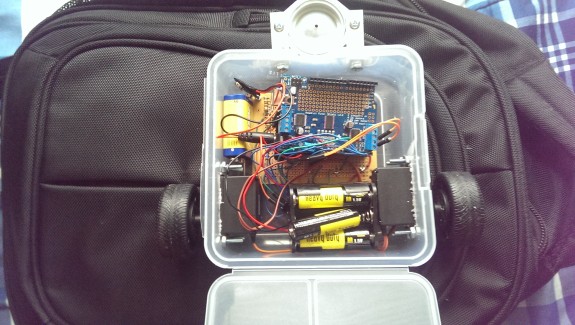
Now to power this robot, I decided to use two separate power sources for the Arduino and for the motor shield since I've online that sharing a power source can sometimes create some problems. For the Arduino, I used a 9V battery to connect through the barrel jack that came with it. For the motor shield, I got my hands on a battery case that I borrowed from my school. The case holds 6 AA batteries that would a final 9V to the motor shield. From reading online, you cannot use a regular 9V battery such as the one I am using for the Arduino. The recommended voltage for the motor shield is 5 to 12 volts so 9 volts is okay. I connect the battery case on the shield where it reads power. In the picture below, all my connections are done. Just that I have not completed the battery connections for the Arduino or the motor shield.

I placed the Arduino on top of the sensor board. I decided to put electrical tape underneath the Arduino as a precaution to avoid any short circuiting of the sensor board and of the Arduino. The battery pack for the motor shield was placed towards the back of the frame as shown. The 9V battery for the Arduino was placed to the side as shown. With the case closed:

The Programming:
For the programming of the Arduino, I first got a code that was already prewritten for the line follower using this setup.
The link to the code is: https://sites.google.com/site/arduinorobotics/home/chapter4_files
But this code was used for an older version of the shield that I am using. So I had to make just a few changes to make the code work. But first I had to download the library for the motor which was found on the website where I ordered the shield from, Adafruit.com. Once the library is downloaded, it is important to copy it to the Arduino's libraries folder. So that's what I did. After copying the library, I made the changes to the code from the link above.
The code is:
// Linus the Line-bot
// Follows a Black line on a White surface(poster-board and electrical type or the floor and tape).
// Code by JDW 2010 - feel free to modify.
// Modified by Gerardo Ramos March 11, 2014
// My first arduino project, first electronic project
#include <Wire.h> // this includes the Afmotor library for the motor-controller
#include <Adafruit_MotorShield.h>
#include "utility/Adafruit_PWMServoDriver.h"
Adafruit_MotorShield AFMS = Adafruit_MotorShield();
Adafruit_DCMotor *motor_left=AFMS.getMotor(1); // attach motor_left to the Adafruitmotorshield M1
Adafruit_DCMotor *motor_right=AFMS.getMotor(3); // attach motor_right to the Adafruitmotorshield M3
// Create variables for sensor readings
int sensor1 = 0;
int sensor2 = 0;
int sensor3 = 0;
int sensor4 = 0;
int sensor5 = 0;
// Create variables for adjusted readings
int adj_1=0;
int adj_2=0;
int adj_3=0;
int adj_4=0;
int adj_5=0;
// You can change the min/max values below to fine tune each sensor
int s1_min=200;
int s1_max=950;
int s2_min=200;
int s2_max=950;
int s3_min=200;
int s3_max=950;
int s4_min=200;
int s4_max=950;
int s5_min=200;
int s5_max=950;
// This threshold defines when the sensor is reading the black line
intlower_threshold=80;
// Value to define a middle threshold(half of the total 255 value range)
int threshold=110;
// This threshold defines when the sensor is reading the white poster board or
// the floor if you are testing it on the floor like I did.
intupper_threshold=200;
// This value sets the maximum speed of linus (max=255).
// using a speed potentiometer will over-ride this setting.
intspeed_value=220;
// End of changeable variables
void setup()
{
Serial.begin(9600); // Start serial monitor to see sensor readings
AFMS.begin();
// declare left motor
motor_left->setSpeed(255);
motor_left->run(RELEASE);
// declare right motor
motor_right->setSpeed(255);
motor_right->run(RELEASE);
}
voidupdate_sensors(){
// This will read sensor 1
sensor1=analogRead(0);
adj_1=map(sensor1,s1_min,s1_max,0,255);
adj_1=constrain(adj_1,0,255);
// This will read sensor 2
sensor2=analogRead(1); // sensor 2 =left-center
adj_2=map(sensor2,s2_min,s2_max,0,255);
adj_2=constrain(adj_2,0,255);
// This will read sensor 3
sensor3=analogRead(2); // sensor 3 =center
adj_3=map(sensor3,s3_min,s3_max,0,255);
adj_3=constrain(adj_3,0,255);
// This will read sensor 4
sensor4=analogRead(3); // sensor 4 = right-center
adj_4=map(sensor4,s4_min,s4_max,0,255);
adj_4=constrain(adj_4,0,255);
// This will read sensor 5
sensor5=analogRead(4); //sensor5 = right
adj_5=map(sensor5,s5_min,s5_max,0,255);
adj_5=constrain(adj_5,0,255);
}
void loop(){
update_sensors(); // update the sensors
// First, check the value of the center sensor
if (adj_3<lower_threshold){
// If center sensor value is below threshold, check surrounding sensors
if (adj_2>threshold && adj_4>threshold){
// If all sensors check out(if statements are satisfied), drive forward
motor_left->run(FORWARD);
motor_left->setSpeed(speed_value);
motor_right->run(FORWARD);
motor_right->setSpeed(speed_value);
}
// You want the line bot to stop when it reaches the black box/
else if (adj_1<30){
if (adj_2<30){
if (adj_3<30){
if (adj_4<30){
if (adj_5<30){
// Here all the sensors are reading black, so stop the bot.
motor_left->run(RELEASE);
motor_right->run(RELEASE);
}
}
}
}
}
}
// Otherwise, the center sensor is above the threshold
// So we need to check what sensor is above the black line
else {
// First check sensor 1
if (adj_1<upper_threshold&& adj_5>upper_threshold){
motor_left->run(RELEASE);
motor_left->setSpeed(0);
motor_right->run(FORWARD);
motor_right->setSpeed(speed_value);
}
// Then check sensor 5
else if (adj_1>upper_threshold&& adj_5<upper_threshold){
motor_left->run(FORWARD);
motor_left->setSpeed(speed_value);
motor_right->run(RELEASE);
motor_right->setSpeed(0);
}
// If not sensor 1 or 5, then check sensor 2
else if (adj_2<upper_threshold&& adj_4>upper_threshold){
motor_left->run(RELEASE);
motor_left->setSpeed(0);
motor_right->run(FORWARD);
motor_right->setSpeed(speed_value);
}
// if not sensor 2, then check sensor 4
else if (adj_2>upper_threshold&& adj_4<upper_threshold){
motor_left->run(FORWARD);
motor_left->setSpeed(speed_value);
motor_right->run(RELEASE);
motor_right->setSpeed(0);
}
}
///// Print values for each sensor
///// Sensor 1 values
Serial.print("Sensor 1: ");
Serial.print(sensor1);
Serial.print(" - ");
Serial.print("Adj 1: ");
Serial.print(adj_1);
Serial.print(" - ");
// Sensor 2 Values
Serial.print("Sensor 2: ");
Serial.print(sensor2);
Serial.print(" - ");
Serial.print("Adj 2: ");
Serial.print(adj_2);
Serial.print(" - ");
// Sensor 3 Values
Serial.print("Sensor 3: ");
Serial.print(sensor3);
Serial.print(" - ");
Serial.print("Adj 3: ");
Serial.print(adj_3);
Serial.print(" - ");
// Sensor 4 Values
Serial.print("Sensor 4: ");
Serial.print(sensor4);
Serial.print(" - ");
Serial.print("Adj 4: ");
Serial.print(adj_4);
Serial.print(" - ");
// Sensor 5 Values
Serial.print("Sensor 5: ");
Serial.print(sensor5);
Serial.print(" - ");
Serial.print("Adj 5: ");
Serial.print(adj_5);
Serial.print(" ");
}
// End of this code
Once I completed the code, I connected my Arduino to my laptop. Then I reopened the code, then compiled to make sure there were no errors. Then I uploaded the code to the Arduino. At this I didn’t have the motor shield powered. So in this way I can see what the sensors are reading. To do this I opened the serial monitor. Turn off autoscroll so you can see what the sensors are reading. So I placed the line follower on the floor to see what it reads. For me, it read the floor at high readings at 255 which is good. It means that it’s reading it as it were a white poster board. I didn’t have a large poster board to test the Arduino so I opted to just my floor.


For my lower threshold I used 80. The original code had 20, which was good but sometimes my sensors didn't read long enough to read below 20. So I used 80. Just compare your readings of the black line to your thresholds. You want the reading of the black line to be lower than the lower threshold value. Here I was experimenting with 50 but it didn't really work out well. Sometimes my middle sensor would directly above the black line but would get a reading of sometimes in the 60's. So the if-else statement didn't work well with the line follower going in a straight line. Some of the reasons why it’s not reading a low enough a number is because maybe the sensors or placed to close or maybe the adjacent sensors are directly perpendicular to the floor. So maybe some of their infrared light is being read by the middle sensor. Whatever the reason was, I had to make increase my lower threshold value.

There are times where my readings are as low as 8 but that isn't the case every time. So I increased my lower threshold to 80. And I also increased my threshold value to 110 just to make sure the if-else statements work. I also decreased my upper threshold value to 200 to allow it to account for slightly darker areas of the floor. The speed of the line follower can be chosen from any range from 0 to the maximum of 255. For me, I used 220. Compare your thresholds with the if-else statements to make sure that everything makes sense to and to figure what numbers you should choose for your setup since every setup is going to be slightly different.

Doing a Test Run:
Now after "calibrating" the line follower it was time to do a test run. At first I was doing a small track but the turns were a little too tight. So I did a bigger track. I used black electrical tape for the track. I made sure the tape was flat all around the track to prevent it from being too high and get in the way of the line follower as I have learned doing it a few times.

There are times were the line follower does go off track but I think it's because it possibly be reading debris on the ground. Well that is the only explanation I can think off. Another issue that I had was that sometimes the turns could be too tight? Such as the at bottom right of my laptop. I figure that with a smaller frame, the robot can execute the turns much better as I have seen on YouTube videos of racing line followers. Well that's it guys until next where I will have video of the line follower in action.
Part 4: A Video Demostration
Hey guys!
I finally got a chance to record the line follower in action. I had to readjust some numbers in the code for it to be able to work. The floor here is different from where I was initially testing the line follower. So, I got different readings from the infrared detectors. But here's a quick video of the line follower. There was a part where the line follower seems to stop but it was because a piece of the tape was sticking out. So it got in the way since the robot has a low clearance to the ground.
It follows a line made of black electrical tape on a light colored floor.