SiLi LiLa BOT (Simple Little Line-following Launchpad Robot)

Posted on 19/05/2013 by fizikus
Modified on: 13/09/2018
Introduction
This is an automatic import from our previous community platform. Some things can look imperfect.

If you are the original author, please access your User Control Panel and update it.

SiLi LiLa BOT (Simple Little Line-following Launchpad Robot)  My aim was to build a cheap and simple line-following robot for beginners. During the design and construction, I tried to keep the robot as simple and cheap to build as possible. I used black electrician’s tape on a white carpet to make the line. The Robot DesignThe first step in the designing process should be the accurate definition of the task of the robot. The Robot's TaskThe task of our robot is simple: follow the ...


SiLi LiLa BOT (Simple Little Line-following Launchpad Robot)

SiLi LiLa BOT (Simple Little Line-following Launchpad Robot)


My aim was to build a cheap and simple line-following robot for beginners.

During the design and construction, I tried to keep the robot as simple and cheap to build as possible. I used black electrician’s tape on a white carpet to make the line.
 
The Robot Design
The first step in the designing process should be the accurate definition of the task of the robot.
 
The Robot's Task
The task of our robot is simple: follow the black line on the white carpet floor. The task looks simple, but in order to solve this problem, we have to divide it into sub-tasks:
- The robot has to detect the line somehow (sensors).
- The robot has to be able to move and turn to follow the line (motors and drive system).
- The robot needs a brain, which reads sensor data and makes decisions and command the motors (microcontroller + programming).
 
The Drive System
To make it simple, the robot will use a differential drive system. For the steering of the robot, this method does not require turning of the front wheels like in cars or bikes. The robot will have two sets of powered wheels and a castor wheel. With a differential drive system the robot’s movement is controlled with the adjustment of the motor’s speed and direction. For example if both motors go forward at the same speed, the robot will go forward too (A). If the right wheel rotates faster than the LEFT wheel, then the robot will turn towards left in an arc (B). If the left motor stops, then the robot will turn around the left wheel (C). If the left and right motors go in the opposite direction, then the robot can turn around over the same spot (D).
 
The line-follower robot needs to control the motor speed accurately to be able to follow the line. For the control of the motors I will use an L293D motor driver chip. The L293D IC can control two DC motors, and it needs 3 input signals to control one motor (1for motor speed, 2 for motor direction). The motor speed can be controlled by supplying a PWM signal (Pulse Width Modulation) to the input enable ENABLE-1 pin of the L293D. The motor direction can be controlled by supplying the appropriate digital signal to the INPUT1 and INPUT2 Pins. The other motor can be controlled similarly by the ENABLE-2 and INPUT3 and INPUT4 Pins. The INPUT signals for each motor has to be the opposite of each other, so by the use of one CD4069 hex inverter IC, the motor direction can be controlled with only 1 input signal.
 
The microcontroller operates with 3.3V, the DC motors, L293D and the hex inverter IC needs minimum 5V and the motors draw big currents from supply. Because of this, I will use separate supplies for the microcontroller and motors. The 4xAA battery (6V) is the main power source for the DC motors, and the 9V battery is the power source for the electronics circuits.
 
The motor speed controlling PWM signal switches on and off the DC motors a couple thousand times each second. Because of this, there was a lot of electrical noise in the system, which made the microcontroller on the Launchpad panel go crazy. I have soldered 0.22 uF ceramic capacitors between the poles of the DC motor to reduce electrical noise, and the L293D chip is already equipped with internal EMF (Electromotive Force) protection diodes. But this was still not enough. I could eliminate the noise only by separating galvanically the microcontroller from the motors and the motor controller parts with a 4 channel optocoupler IC.
 
The final version of the motor controller circuit looks like this:
 
The Line Sensor
For the line sensor I decided to use a white LED + LDR pair. The Light Dependent Resistor (LDR) will detect the black line. The Light Emitting Diode (LED) sends a constant beam of white light towards the ground. This light is reflected back to the LDR. Depending on the colour of the ground, the LDR receives varying amounts of reflected light. The more light that gets to the LDR, the less of its resistance will be. The microcontroller can only detect voltages, so we have to find a way to convert this resistance change into a voltage change. We can do it with a voltage divider circuit, which will provide the varying voltage according to the amount of the light intensity reflected back to the LDR.
 
 
When the sensor is above the white background, then most of the white LED’s light will reflected back to the LDR and the LDR’s resistance value will be low, high amount of current will flow through the LDR and the serially connected R resistor and big voltage will appear between the output and GND. If the sensor is above the black line, then small amount of  light will reflected back to the LDR and the LDR’s resistance will be high, low amount of current will flow through the LDR and the R resistor and small voltage will appear between the output and GND.
 
 
The Microcontroller
As the brain for controlling the robot I used a Launchpad panel with an MSP430G2553 microcontroller.
 

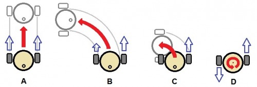
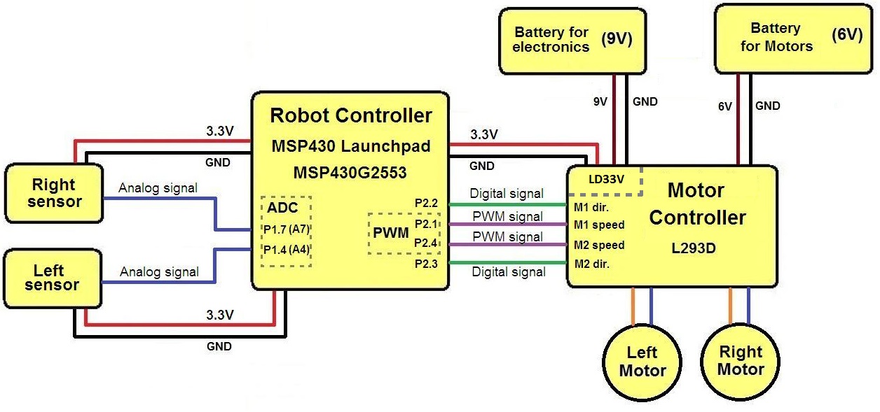
Block diagram of the Robot

Now I can summarize the robot design:

- The robot uses two DC motors and a castor wheel in a differential drive configuration (the steering of the robot is done by adjusting the speed of the motors).

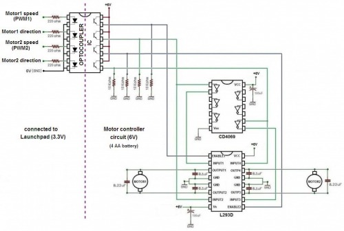
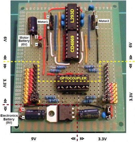
- The speed and direction of the motors are controlled with PWM and digital signals by an L293D motor driver IC.

- The robot uses two battery (one for the electronics and one for the DC motors and motor controller circuits)

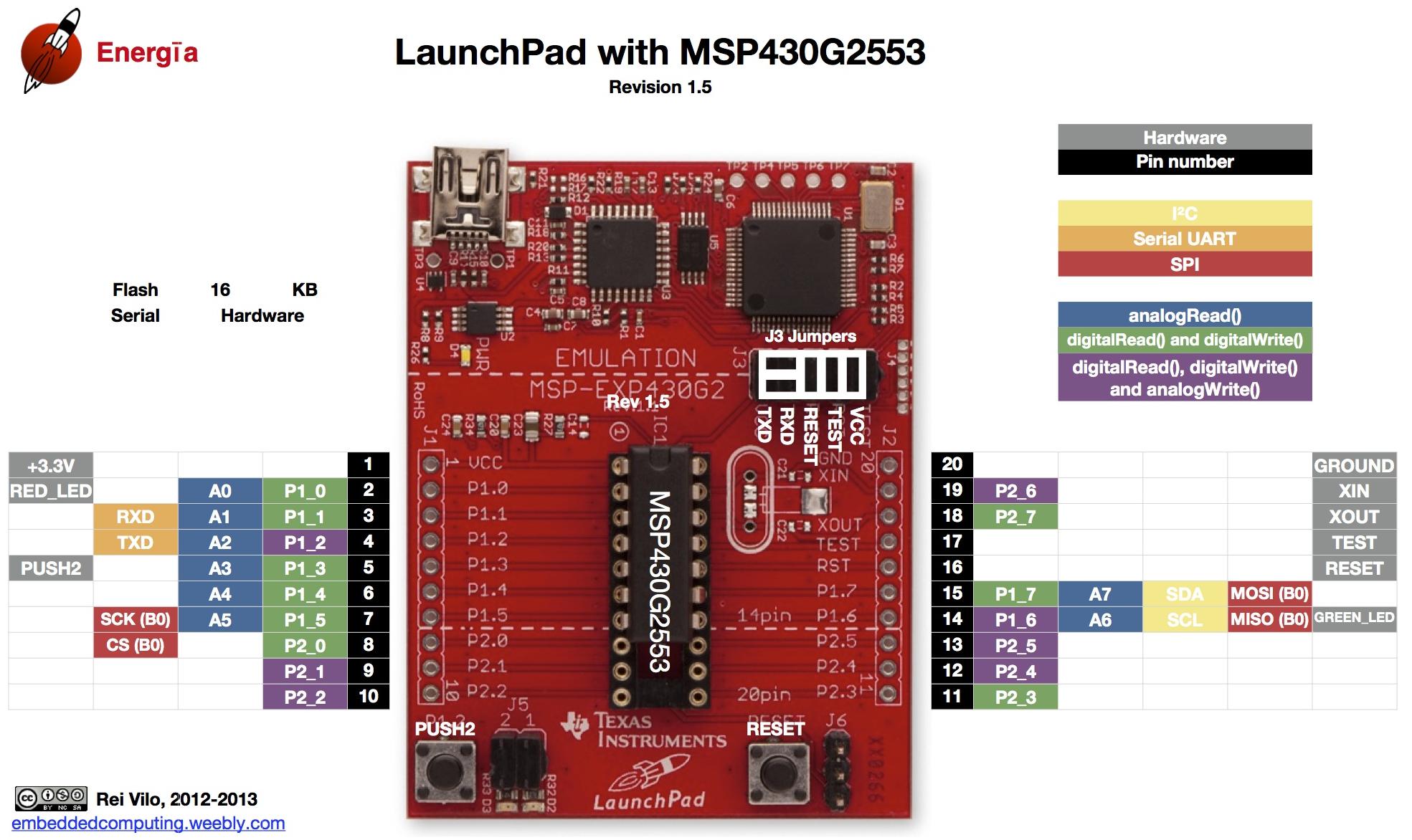
- The robot uses a Launchpad panel with a MSP430G2553 microcontroller

- The robot uses two sensors to determine the position of the black line beneath the robot.

By adjusting the speed of the two DC motors based on the sensor readings, the microcontroller can keep the line between the two sensors, and the robot could drive around the track.

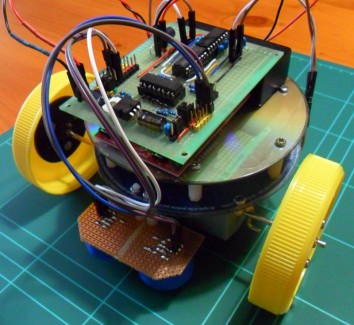
Construction of the Robot

As the design is finalized, I can start building the robot.

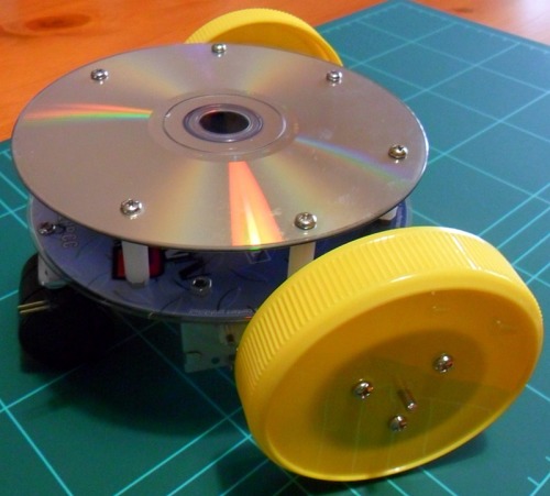
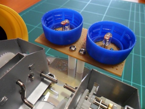
Construction of the robot frame

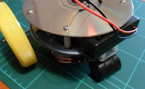
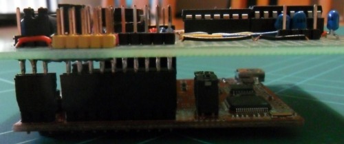
The robot frame is made of two CD/DVDs to give enough structural strength. The lower deck will hold the 6V motor battery, two line detecting sensor, two DC motors and the castor wheel. The upper deck will hold the motor controller circuit attached to the Launchpad board and the 9V electronics battery.


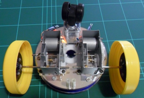
The wheels are made from the lid of peanut butter jars.

There is enough space between the two decks to hold the motor battery pack.


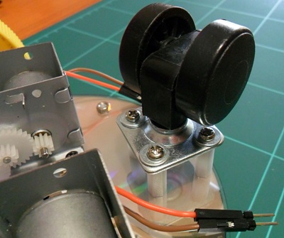
The castor wheel should rotate freely around.


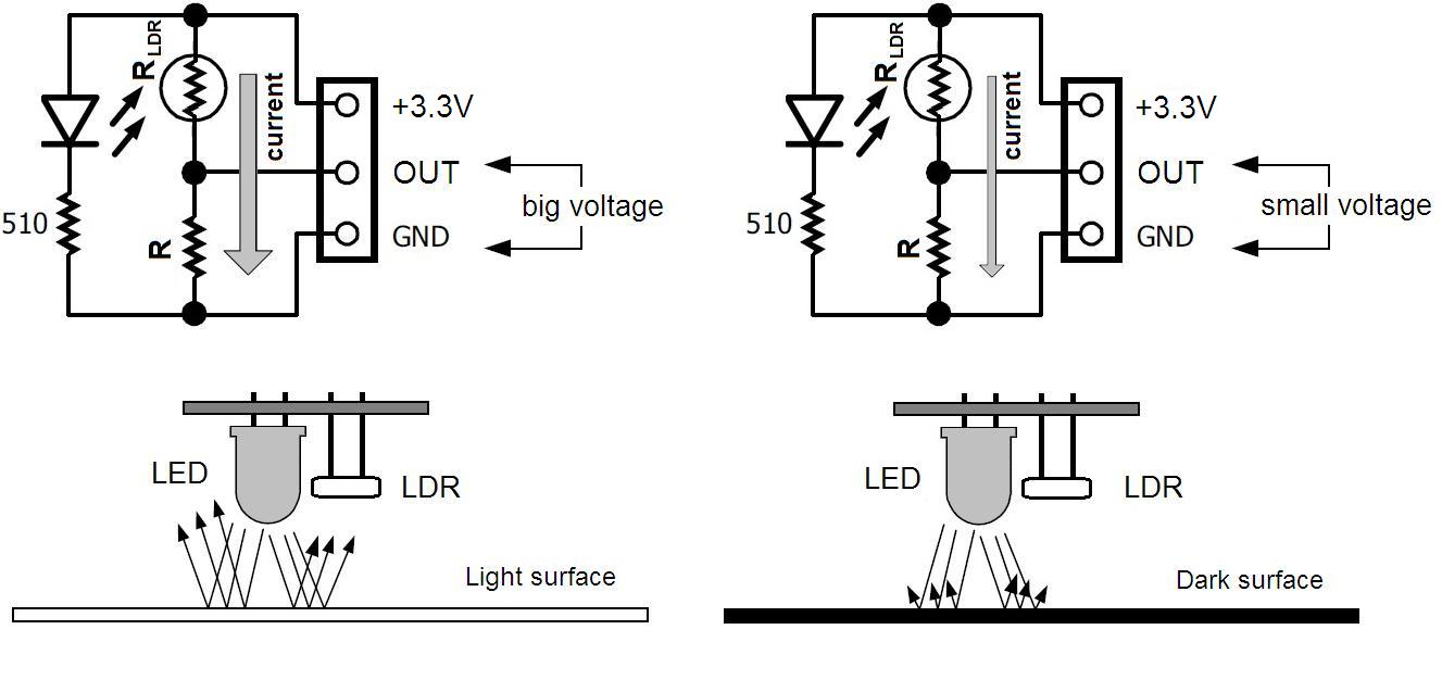
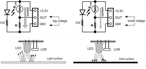
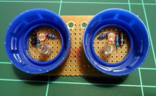
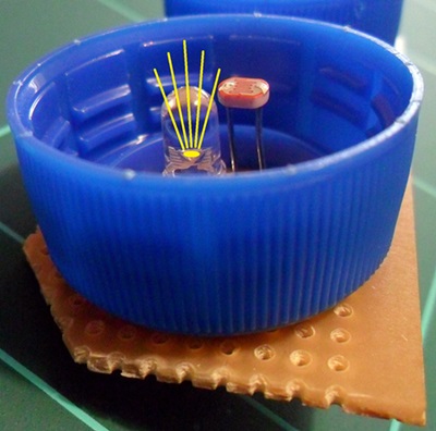
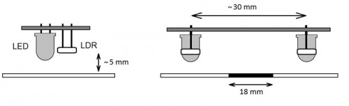
Construction of the Line Sensor

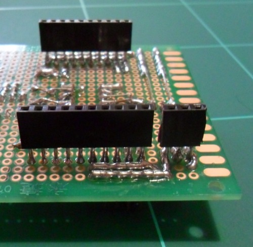
The sensors (LDR and LED pair) are assembled on a small perforated PCB. 

I have positioned the LDR a little bit more forward (closer to the floor) compared to the LED to make sure no direct light could reach the LDR, only the ones that reflected back from the floor. 
I have placed my sensors about 3cm apart, and about 5mm from the floor. To shield the sensors from the ambient light, I used plastic bottle caps.
Construction of the Motor Controller Panel
I have assembled the motor controller circuit on a perforated PCB. You can see at the picture below, that I have divided the circuit into different sections. The LD1117V33 voltage regulator makes 3.3V from the 9V of the electronics battery. I used extended headers and female headers to connect to the Launchpad Pins. To make connecting sensors to the panel easier, I put headers with 3.3V(red headers) and GND(yellow headers) next to the Launshpad Pins. The optocoupler separates the 3.3V section from the 6V motor controller section. On the panel I have used jumpers to connect two PWM capable Launchpad pins (P2.1 and P2.4) and two digital Launchpad pins (P2.2 and P2.3) to the appropriate pins of the motor controller circuit for speed and direction control of the two DC motors.
The extended header and the female headers make it possible to connect the motor controller to the Launchpad panel. 

After connecting the left sensor to Pin6 (P1.4), the right sensor to Pin15 (P1.7) and connecting the 9V battery and 6V battery pack to the proper Pins, the building of the robot is finished. 

The next step will be the programming.

The Line-following Algorithm 

Before we could program the robot, we have to find an appropriate line following algorithm. At first we have to make test measurements with the line following sensor to be able to decide when a sensor is over the black line or the white carpet. Without switching on the electronics and motor power supply, I have connected the Launchpad panel to the PC with the USB cable to power the microcontroller and the line sensor. I have compiled and uploaded the attached code with the Energia IDE into the Launchpad panel (See next paragraph about the Energia IDE). The code reads the left and right sensor data and sends them to the PC via serial communication. The values can be displayed with the serial monitor.


If the sensor was over the black line, the measured ADC values were around 665-675. If the sensor was over the carpet, than the values were around 775-785. So we can use 720 as treshold value. If a sensor value is smaller than 720, then the sensor is over the line. If the sensor value is greater then 720, then it is over the carpet.


Now that we can decide when a sensor is over a line or the background, we can find a line following algorithm.


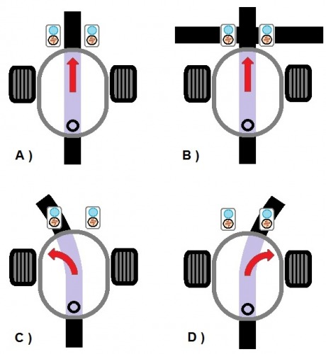
The microcontroller should read the sensor data, and based on that readings it should adjust the speed of the two DC motors to keep the line between the two sensors. So the robot could drive around the track. If the left sensor is over the line (the left sensor value is smaller than the 720 threshold value), than the robot should turn left (C). Similarly if the right sensor is over the line (the right sensor value is smaller than 720), than the robot should turn right (D). If both sensor value is greater than the threshold (the line is between the two sensors - A), or if both sensor value is smaller than the threshold (the robot approached to a line crossing - B), than the robot should go forward. To prevent oscillation, it is good idea to wait a couple ms before the next sensor measurement.


 The line following algorithm displayed on a flowchart:


We should code this algorithm to Launchpad with the Arduino like Energia IDE.


The Energia IDE 

Energia is an open-source electronics prototyping platform, which brings the Wiring and Arduino framework to the Texas Instruments MSP430 LaunchPad.


About downloading and installing the Energia IDE and about how to set up your board, see the following site:

https://github.com/energia/Energia/wiki/Getting-Started


About how to set up serial communication:

https://github.com/energia/Energia/wiki/Serial-Communication


Loading the Code

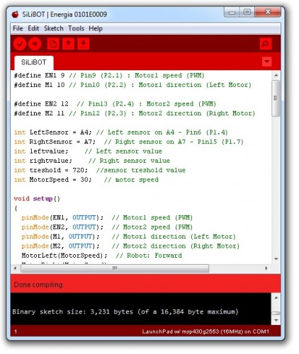
Now the robot is nearly finished, it is time to load the code to the Launchpad panel. Make sure, that the MSP2553 chip is in the panel, and that the MSP2553 chip is selected from the “Tools/Board” menu (the attached code is for MSP430G2553 only, because this chip supports hardware UART, if you use other MSP430 Chips, which supports software UART only, than you have to use software serial communication softserial() in the Energia code instead of serial() ). Open the Energia IDE and copy the code from the attached text file into a blank sketch. After copied, press the Compile button to make sure there are no errors. Press the Upload button to load the compiled code into the Launchpad panel.


Understanding the Code

The Energia language is an implementation of Arduino to the Launchpad. So most of the Arduino projects and codes with small modofications can be directly transfered to the Launchpad.

In the main program, the loop() infinite cycle continously reading the left and right sensor data with the analogRead() command into two variables named LeftLDR and RightLDR. The if() and else if() commands decide which sensors are over the line or the carpet. Based on these decisions the microcontroller controls the motors according to the line following algorithm to keep the line between the two sensors.

To make the controlling of the robot easier, I have made the MotorLeft() and MotorRight() motor controlling functions. These functions need a parameter between -100 and 100 to control a motor (reverse 100% - forward 100%). In these motorcontroller functions, the motor direction is adjusted with the digitalWrite() command, and the motor speed is adjusted with the analogWrite() command.

 THE END (Finally...)

Bye: Fizikus

Following a black line on white carpet.

  • Actuators / output devices: 2 geared DC motors + castor wheel
  • CPU: Msp430g2553
  • Operating system: Energia IDE (Windows)
  • Power source: 9V battery for electronics, 6V battery (4xAA) for motors
  • Programming language: Energia IDE
  • Sensors / input devices: white LED + LDR pair
  • Target environment: indoor
LikedLike this to see more

Spread the word

Flag this post

Thanks for helping to keep our community civil!


Notify staff privately
It's Spam
This post is an advertisement, or vandalism. It is not useful or relevant to the current topic.

You flagged this as spam. Undo flag.Flag Post