


Self Balancing Robot Using Mpu6050 Accelerometer
hello guys..this is our project..
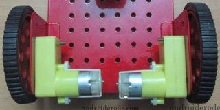
this is self balancing robot on two wheels using mpu6050 accelerometer..
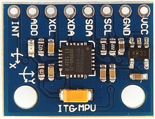
The MPU 6050 is a 6 DOF (Degrees of Freedom) or a six-axis IMU sensor, which means that it gives six values as output. Three values from the accelerometer and three from the gyroscope. TheMPU 6050 is a sensor based on MEMS (Micro Electro Mechanical Systems) technology...
so our next generation two wheeler byke...that will be self balanced.and also cycle.
in this project mainly used arduino uno thats as microcontroller..
Step 1: Components
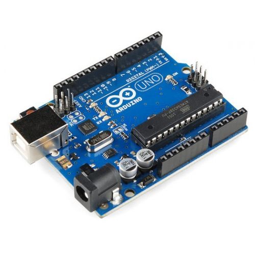

1:-arduino uno
2:-mpu6050 accelerometer
3:-mini breadboard
4:-two dc motors
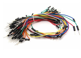
5:-jumper wires
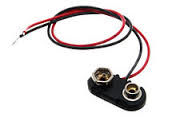
6:-9v battery
7:-battery jack
8:-l293d motor driver
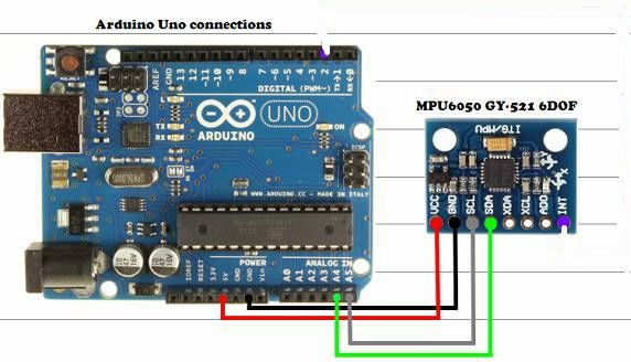
Step 2: Mpu6050 Connection
to this accelerometer
we have 4pins will be used for this project.....
so vcc pin of mpu6050 is connect to +5v
and gnd pin of mpu6050 is connect to gnd
and scl,sda pin of mpu6050 is connect to analog pin of arduino...
Step 3: If You Used As L293d Ic
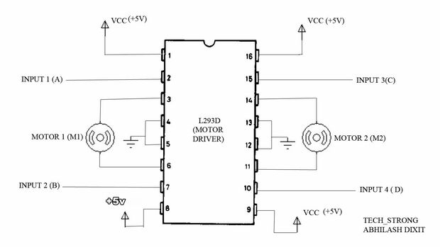
if you use l293d ic instead of l293d motor driver..
even its will be easy for connection...
. l293d ic have 16pin... 1,8,9 and 16 pin connect to +5v.
and 4,5,12,13 pin connect to gnd...
input 1,2,3 and 4pin is connect to arduino pin..
output is connect to left motor and right motor..
input 1 and 2 is connect for left motor..
and input 3 and 4 is connect for right motor..
Step 4: Circuit Diagram
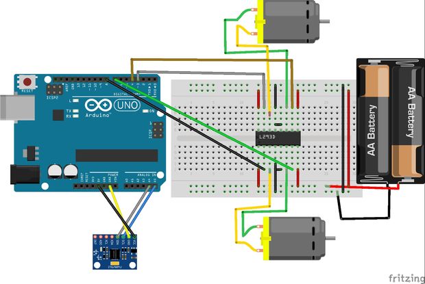
here ...........
arduino analog pins:a5 and a4
and digital pin:-3,6,11,14...
a5 analog pin...............connected to the....SCL pin of mpu6050
a4 analog pin ............connected to the......SDA pin of mpu6050.
8pin of arduino..............2pin of l293d
7pin of arduino.............7pin of l293d
4pin of arduino.............10pin of l293d
3pin of arduino............15pin of l293d
so..this 8,7,4 and 3 pin connected to the l293d motor driver..
and 9v battery also connected to vcc and gnd..
Step 5: Working Principle
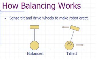
The physics for this robot are simple, the robot stand in two points lined, the wheel, and i tends to fall and lose his verticality, the movement of the wheel in the direction of the falling rises the robot for recover the vertical position.
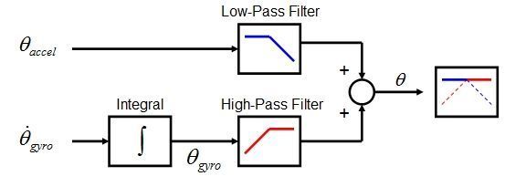
A Segway-type vehicle is a classic inverted pendulum control problem that is solvable in two degrees of freedom for the simplest models. The vehicle attempts to correct for an induced lean angle by moving forward or backwards, and the goal is to return itself to vertical. Or at least not fall over. For that objective we have two things to do, in one hand we have to measure the angle of inclination (Roll) that have the vehicle, and in the other hand we have to control the motors for going forward or backwards to make that angle 0, maintaining his verticality. Angle Measurement: For measure the angle we have two sensors,
accelerometer and gyroscope, both have his advantages and disadvantages. The accelerometer can measure the force of the gravity, and with that information we can obtain the angle of the robot, the problem of the accelerometer is that it can also measure the rest of the forces the vehicle is someted, so it has lot of error and noise.
The gyroscope measure the angular velocity, so if we integrate this measure we can obtain the angle the robot is moved, the problem of this measure is that is not perfect and the integration has a deviation, that means that in short time the measure is so good, but for long time terms the angle will deviate much form the real angle.
Those problems can be resolved be the combination of both sensors, that's called sensor fusion, and there are a lot of methods to combine it. In this project i try two of them: Kalman Filter, and complementary filter..
1:-The Kalman filter is an algorithm very extended in robotics, and offers a good result with low computational cost. There is a library for arduino that implements this method.
2:-The Complementary filter is a combination of two or more filters that combines the information from different sources and gets the best value you want. It can be implement in only one line of code
Step 6: Uploading Code
here..
two coding is needed for this project..
some screenshot will help you..
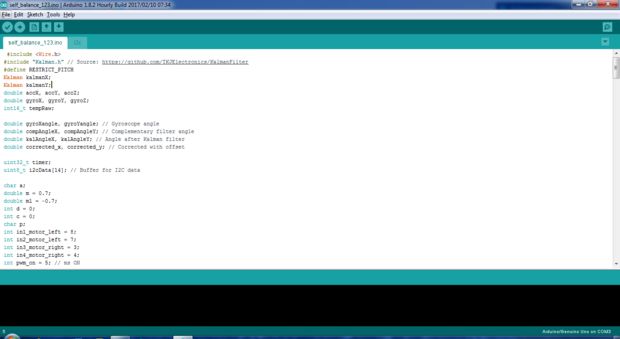
1st code save as selfbalance.ino......
#include
#include "Kalman.h" // Source: https://github.com/TKJElectronics/KalmanFilter#define RESTRICT_PITCH Kalman kalmanX; Kalman kalmanY; double accX, accY, accZ; double gyroX, gyroY, gyroZ; int16_t tempRaw;
double gyroXangle, gyroYangle; // Gyroscope angle double compAngleX, compAngleY; // Complementary filter angle double kalAngleX, kalAngleY; // Angle after Kalman filter double corrected_x, corrected_y; // Corrected with offset
uint32_t timer; uint8_t i2cData[14]; // Buffer for I2C data
char a; double m = 0.7; double m1 = -0.7; int d = 0; int c = 0; char p; int in1_motor_left = 8; int in2_motor_left = 7; int in3_motor_right = 3; int in4_motor_right = 4; int pwm_on = 5; // ms ON int pwm_off = 5; // ms OFF //------------------------------------------------------------------------------ void setup() { // Define outputs pinMode(in1_motor_left, OUTPUT); pinMode(in2_motor_left, OUTPUT); pinMode(in3_motor_right, OUTPUT); pinMode(in4_motor_right, OUTPUT); // Start serial console Serial.begin(115200); //BT.begin(9600); delay(50); // Initiate the Wire library and join the I2C bus as a master or slave Wire.begin();
TWBR = ((F_CPU / 400000L) - 16) / 2; // Set I2C frequency to 400kHz
i2cData[0] = 7; // Set the sample rate to 1000Hz - 8kHz/(7+1) = 1000Hz i2cData[1] = 0x00; // Disable FSYNC and set 260 Hz Acc filtering, 256 Hz Gyro filtering, 8 KHz sampling i2cData[2] = 0x00; // Set Gyro Full Scale Range to ±250deg/s i2cData[3] = 0x00; // Set Accelerometer Full Scale Range to ±2g
while (i2cWrite(0x19, i2cData, 4, false)); // Write to all four registers at once while (i2cWrite(0x6B, 0x01, true)); // PLL with X axis gyroscope reference and disable sleep mode
while (i2cRead(0x75, i2cData, 1)); if (i2cData[0] != 0x68) { // Read "WHO_AM_I" register Serial.print(F("Error reading sensor")); while (1); } delay(100); // Wait for sensor to stabilize
/** * Set kalman and gyro starting angle * */ while (i2cRead(0x3B, i2cData, 6)); accX = (i2cData[0] << 8) | i2cData[1]; accY = (i2cData[2] << 8) | i2cData[3]; accZ = (i2cData[4] << 8) | i2cData[5];
// atan2 outputs the value of -π to π (radians) - seehttp://en.wikipedia.org/wiki/Atan2 // It is then converted from radians to degrees #ifdef RESTRICT_PITCH double roll = atan2(accY, accZ) * RAD_TO_DEG; double pitch = atan(-accX / sqrt(accY * accY + accZ * accZ)) * RAD_TO_DEG; #else double roll = atan(accY / sqrt(accX * accX + accZ * accZ)) * RAD_TO_DEG; double pitch = atan2(-accX, accZ) * RAD_TO_DEG; #endif
kalmanX.setAngle(roll); kalmanY.setAngle(pitch); gyroXangle = roll; gyroYangle = pitch; compAngleX = roll; compAngleY = pitch; timer = micros(); }
//------------------------------------------------------------------------------ void loop() { while (i2cRead(0x3B, i2cData, 14)); accX = ((i2cData[0] << 8) | i2cData[1]); accY = ((i2cData[2] << 8) | i2cData[3]); accZ = ((i2cData[4] << 8) | i2cData[5]); tempRaw = (i2cData[6] << 8) | i2cData[7]; gyroX = (i2cData[8] << 8) | i2cData[9]; gyroY = (i2cData[10] << 8) | i2cData[11]; gyroZ = (i2cData[12] << 8) | i2cData[13]; // Calculate delta time double dt = (double)(micros() - timer) / 1000000; timer = micros();
#ifdef RESTRICT_PITCH double roll = atan2(accY, accZ) * RAD_TO_DEG; double pitch = atan(-accX / sqrt(accY * accY + accZ * accZ)) * RAD_TO_DEG; #else double roll = atan(accY / sqrt(accX * accX + accZ * accZ)) * RAD_TO_DEG; double pitch = atan2(-accX, accZ) * RAD_TO_DEG; #endif
double gyroXrate = gyroX / 131.0; // Convert to deg/s double gyroYrate = gyroY / 131.0; // Convert to deg/s
#ifdef RESTRICT_PITCH // This fixes the transition problem when the accelerometer angle jumps between -180 and 180 degrees if ((roll < -90 && kalAngleX > 90) || (roll > 90 && kalAngleX < -90)) { kalmanX.setAngle(roll); compAngleX = roll; kalAngleX = roll; gyroXangle = roll; } else kalAngleX = kalmanX.getAngle(roll, gyroXrate, dt); // Calculate the angle using a Kalman filter
if (abs(kalAngleX) > 90) gyroYrate = -gyroYrate; // Invert rate, so it fits the restriced accelerometer reading kalAngleY = kalmanY.getAngle(pitch, gyroYrate, dt); #else // This fixes the transition problem when the accelerometer angle jumps between -180 and 180 degrees if ((pitch < -90 && kalAngleY > 90) || (pitch > 90 && kalAngleY < -90)) { kalmanY.setAngle(pitch); compAngleY = pitch; kalAngleY = pitch; gyroYangle = pitch; } else kalAngleY = kalmanY.getAngle(pitch, gyroYrate, dt); // Calculate the angle using a Kalman filter
if (abs(kalAngleY) > 90) gyroXrate = -gyroXrate; // Invert rate, so it fits the restriced accelerometer reading kalAngleX = kalmanX.getAngle(roll, gyroXrate, dt); // Calculate the angle using a Kalman filter #endif
gyroXangle += gyroXrate * dt; // Calculate gyro angle without any filter gyroYangle += gyroYrate * dt; compAngleX = 0.93 * (compAngleX + gyroXrate * dt) + 0.07 * roll; // Calculate the angle using a Complimentary filter compAngleY = 0.93 * (compAngleY + gyroYrate * dt) + 0.07 * pitch;
// Reset the gyro angle when it has drifted too much if (gyroXangle < -180 || gyroXangle > 180) gyroXangle = kalAngleX; if (gyroYangle < -180 || gyroYangle > 180) gyroYangle = kalAngleY; delay(2); Serial.println(); // Corrected angles with offset corrected_x=kalAngleX-171,746; corrected_y=kalAngleY-81,80; corrected_y = corrected_y+84; Serial.print(corrected_y); pwm_adjust(corrected_y); if(corrected_y>=m && corrected_y<20){ if(c>6){ m-=0.2; m1-=-0.2; c=0; } backward(); } else if(corrected_y>=-20 && corrected_y<=m1){ Serial.print(" "); if(d>6){ m+=0.2; m1+=0.2; d=0; } forward(); }else{ stop(); m=0.7; m1=-0.7; pwm_on = 0; pwm_off = 0; }
}
void forward(){ d++; //Serial.print(d); digitalWrite(in3_motor_right, LOW); digitalWrite(in4_motor_right, HIGH); digitalWrite(in1_motor_left, HIGH); digitalWrite(in2_motor_left, LOW); delay(pwm_on);
digitalWrite(in3_motor_right, LOW); digitalWrite(in4_motor_right, LOW); digitalWrite(in1_motor_left, LOW); digitalWrite(in2_motor_left, LOW); delay(pwm_off); }
void backward(){ c++; digitalWrite(in3_motor_right, HIGH); digitalWrite(in4_motor_right,LOW); digitalWrite(in1_motor_left, LOW); digitalWrite(in2_motor_left, HIGH); delay(pwm_on);
digitalWrite(in3_motor_right, LOW); digitalWrite(in4_motor_right, LOW); digitalWrite(in1_motor_left, LOW); digitalWrite(in2_motor_left, LOW); delay(pwm_off); }
void stop(){ digitalWrite(in1_motor_left, LOW); digitalWrite(in2_motor_left, LOW); digitalWrite(in3_motor_right, LOW); digitalWrite(in4_motor_right, LOW); delay(pwm_on);
digitalWrite(in1_motor_left, LOW); digitalWrite(in2_motor_left, LOW); digitalWrite(in3_motor_right, LOW); digitalWrite(in4_motor_right, LOW); delay(pwm_off); } void pwm_adjust(int value_y){ if(value_y >=-1 && value_y <=1 ){ int k = (value_y*value_y); Serial.print(k); pwm_on = 5; // ms ON pwm_off = 3; // ms OFF } else if((value_y>=-3 && value_y<-1)||(value_y>1 && value_y<=3) ){ pwm_on = 50; pwm_off = 5; } else if(value_y >5 || value_y <=-5 ){ Serial.print("**"); pwm_on = 120; // ms ON pwm_off = 3; // ms OFF } else stop(); }
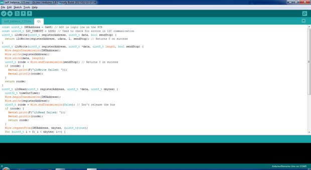
and next to new tab..save as i2c.ino...
const uint8_t IMUAddress = 0x68; // AD0 is logic low on the PCB
const uint16_t I2C_TIMEOUT = 1000; // Used to check for errors in I2C communication uint8_t i2cWrite(uint8_t registerAddress, uint8_t data, bool sendStop) { return i2cWrite(registerAddress, &data, 1, sendStop); // Returns 0 on success } uint8_t i2cWrite(uint8_t registerAddress, uint8_t *data, uint8_t length, bool sendStop) { Wire.beginTransmission(IMUAddress); Wire.write(registerAddress); Wire.write(data, length); uint8_t rcode = Wire.endTransmission(sendStop); // Returns 0 on success if (rcode) { Serial.print(F("i2cWrite failed: ")); Serial.println(rcode); } return rcode; } uint8_t i2cRead(uint8_t registerAddress, uint8_t *data, uint8_t nbytes) { uint32_t timeOutTimer; Wire.beginTransmission(IMUAddress); Wire.write(registerAddress); uint8_t rcode = Wire.endTransmission(false); // Don't release the bus if (rcode) { Serial.print(F("i2cRead failed: ")); Serial.println(rcode); return rcode; } Wire.requestFrom(IMUAddress, nbytes, (uint8_t)true); for (uint8_t i = 0; i < nbytes; i++) { if (Wire.available()) data[i] = Wire.read(); else { timeOutTimer = micros(); while (((micros() - timeOutTimer) < I2C_TIMEOUT) && !Wire.available()); if (Wire.available()) data[i] = Wire.read(); else { Serial.println(F("i2cRead timeout")); return 5; // This error value is not already taken by endTransmission } } } return 0; // Success }
Step 7: Result
copy the 1st code and paste...the try to compile..
the open new tab and upload 2nd code..and alse compile the code....
then compile full code..and upload to arduino..
Step 8:-result
to make this project in full description
follow this link our self balancing robots video in action..