ScoutBot 1402 (an Outdoor Robot)
ScoutBot 1402 is a Robot Designed to take camping with Boy Scout Troop 1402.
It is a rather large and heavy Robot, it stands about 5 feet tall, and weighs in at about 300 pounds. In the photo above, it is resting on a mover's dolly, so that it can be easily moved about the garage when not powered up. I took a new photo of it since I reached the milestone of not having any bare plywood remaining on the frame. The upper arms and shoulder joints were recently reworked, and could now be painted.
The latest mechanical work involves installing the two motors for what I call "shoulder rotation" of the arms, different from the "shoulder lift" motion using the Drums and Cable. This means that the only remaining articulations to be motorized are the gripper open/close movements.
I have also added a VGA video display in the torso that flips out and turns on. I have also created a "manual control" panel to test the arm's mechanical movements, without the complication of computer control.
The ScoutBot is due to visit a school in about 3 weeks, so I buttoned it back up, and did some testing of WiFi communications for remote joystick control.
Currently a work in progress, the main focus of construction right now is finishing up the mechanicals. It does not matter how good your software and electronics are, if you have sloppy and faulty mechanics, the robot will not perform well. The arms have recently been fit with the motors for the Shoulder Lift and Elbow Rotation movements. I have posted a YouTube video here: Click Here to Watch a Video of Arm Movement Tests
(on a side note, to make things sound way cooler than they really are, when people ask me what I made the robot out of, I tell them it is constructed from "ply-tanium")
It is a dual tracked, humaniod torso robot. It's drive train is made from Rexnord 1864 stainless steel table top chain, and is driven by a pair of 24V electric scooter motors. Even with it's weight, it can move as fast as a person does at a brisk walk.
People ask about the "tank tracks" a lot. The first set of "bogies" or track suspension did not work out so well, the robot was simpy too heavy for them to withstand the abuse. I had to completely re-engineer the suspension, which now looks like this:
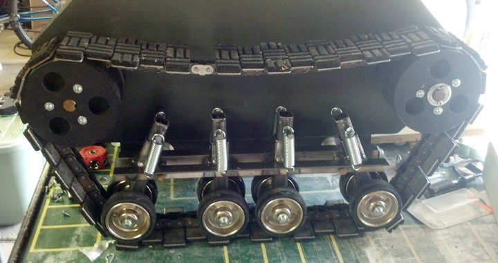
Click Here to Watch the Tracks Run on a Test Bench;
The Drive Wheels are made from more 3/4 inch ply-tanium circle cut using a router table, and then sandwiched onto a #60 chain sprocket:
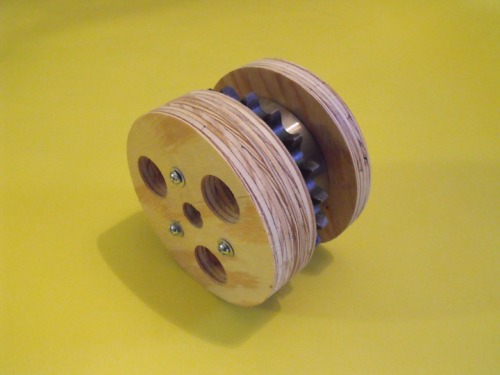
Here is a test fitting of the Rexnord Table Top Chain onto the Drive Wheels and Bogies:
Here is a shot of the Drive Train Motors:
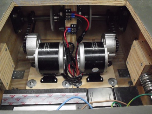
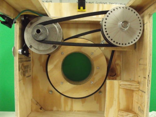
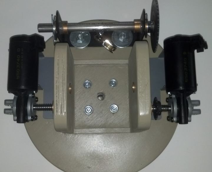
The Torso "shoulder" can rotate, and is driven by an 24V old Electric Scooter Motor, and the arms are driven by automobile seat positioning motors, but they are not installed in the main photo.
Here are the belts, pulleys and drive motor for the rotating shoulder:
Currently, the track drive, upper torso and the head tilt and swivel now have computer interfaces (although I think I just fried the Pololu SMC board last night for the upper torso, I will have to pull it out and check it over). Tests on the arms are being conducted under manual control, since the 'bot is large, heavy and potentially dangerous. The computer control is being done using a conventional PC motherboard, mounted in the lower drive unit. Since I am a software engineer by profession, I can't wait until we have everything interfaced and ready to go "live" on it's own. Missing now are motors and controllers for the Left and Right Shoulder Rotation, controllers for the shoulder "lift" and elbow "rotate", controllers for left and right wrist rotation, and linear actuators for left and right claws.
A user named noonv asked to see closer images of the ScoutBot manipulators. These are fairly primative "claws", the idea being that Boy Scouts in the troop can design and bolt on "new and improved" manipulators as part of earning their Robotics Merit Badge. As with most of ScoutBot, the manipulators are made from Ply-tanium:
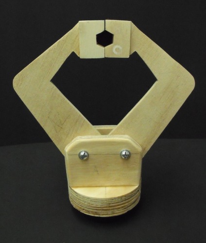
The gripper is designed to be rotated at the "wrist" with a gearmotor, and the "claws" close when a cable is pulled through the center axis of the "wrist". This design allows for full, unlimited 360 degree spinning of the claw without tangles. The claws are spring tensioned to "open" when the cable is relaxed. Here they are with more work done on them:
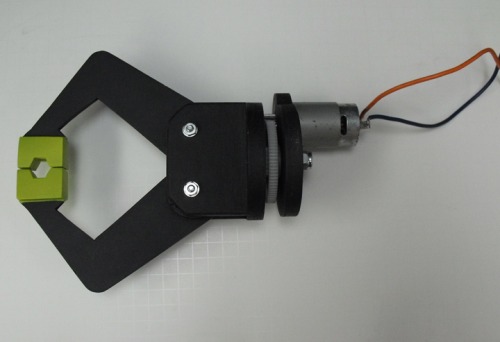
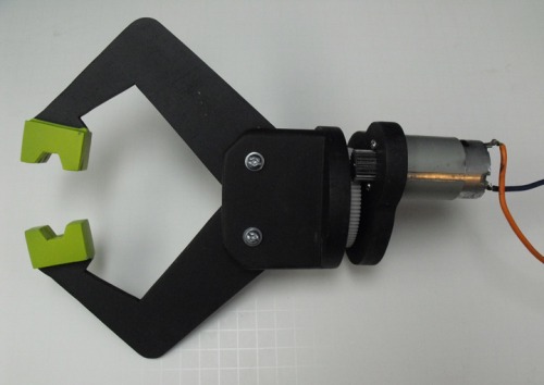
Here is a photo updating the work on the arms, which have been reworked to make use of a "drum/cable" articulation system:
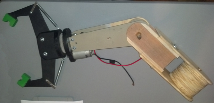
The Rotating Shoulder base holds the motors for the cable drive that actuates the Shoulder Lift and Elbow movements.
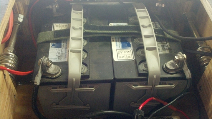
The Robot's main power source is a pair of 12V Wheelchair batteries, wired for 24V:
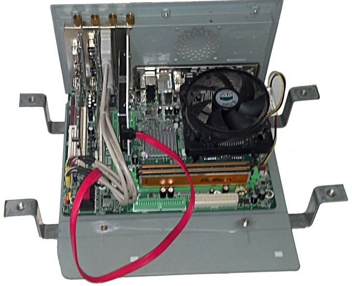
The robot is controlled by a conventional PC Motherboard, currently running Windows XP, but I have run the service on both Windows 7 and 8, so I can update the robot later, should I ever feel the need. Here is the Motherboard Chassis, with modifications to mount in the drive section, positioned right above the battery pack:
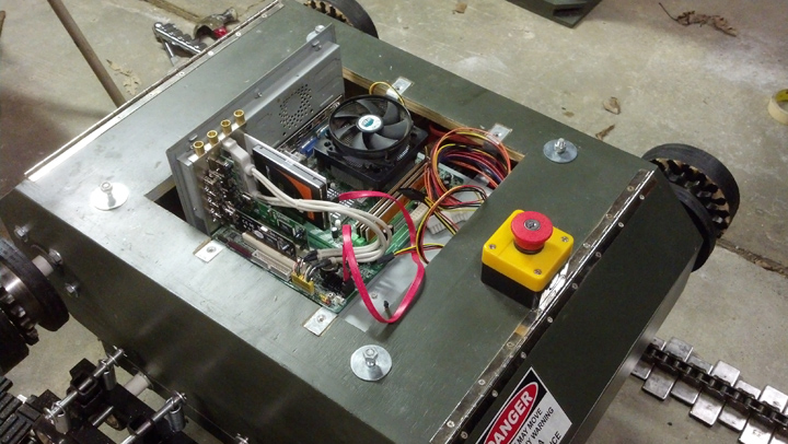
This is what it looks like mounted in the drive section:
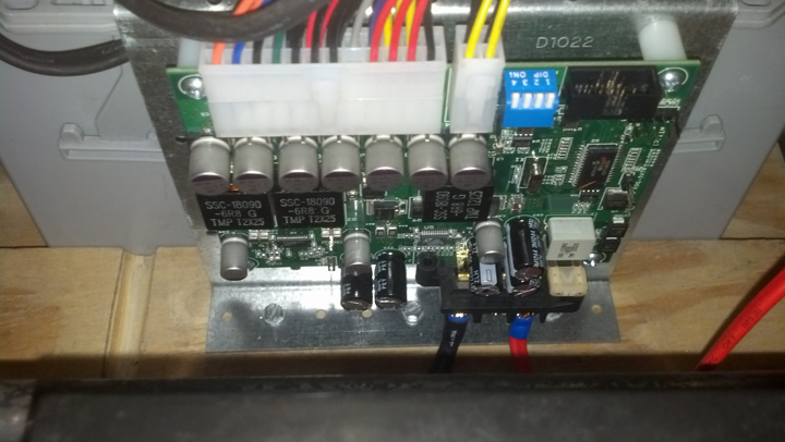
Here is the 24 Volt to PC Power supply, which can run the PC on as little as 12V input:
I finally have a YouTube account, so you can see some videos here:
Watch the Track Drive Run on a Test Bench
Watch the Initial Manual Control Tests
Assists Boy Scouts with Camping Activities
- Actuators / output devices: Electric Scooter and Automotive Power Seat and Window Motors
- Control method: autonomous when finished
- CPU: Intel Core 2 Duo
- Operating system: Windows
- Power source: Bank of Four 12 Volt Scooter Batteries Wired for 24 Volts
- Programming language: C#, VB.NET 2010
- Sensors / input devices: web cam
- Target environment: Indoor or outdoor


