


Sandy the sandbox robot
Videos posted of sandy in operation. (3-1-2012)
This is my first attempt at robotics and the first time here at LMR so apologies if all this is obvious to everyone, but these are notes I made as I went and this seemed a good place to put them, the demented ravings of a time-starved dad!
==================================================================================================
I've been thinking about building a robot for some time but the investment in time to overcome the mechanical/electronic/software hurdles always seemed too great, especially with a young family. However, it seems that many sensors and actuators can now be bought off-the shelf so I decided it was time to give it a punt.
I'd like to experiment with a programmable microcontroller based device so decided to set about building a platform that would enable me to do some tinkering with robotics. Such a platform should have an array of sensors and actuators onto which a microcontroller could be easily added to drive it. So my self-set goal here is:
Goal: Build a generic robotic platform suitable for experimentation.
Mechanics and Electronics
I'm keen to separate the mechanical parts from the electronic parts in this robot. Spending a bit of time up-front build the mechanical section completed with (possibly) more sensors and actuators than I need initially will mean I can concenrate on the electronics/software side and upgrade to larger microcontrollers without having to rebuild the whole mechanical infrastructure. This is to be my development platform, used as a sandbox to try ideas.
With this goal in mind, I decided to make a robot sandwich. The chassis should contain motors, batteries and those sensors that I think may be useful and these should all be brought out to a pluggable interface. If possible, room should be left available to add new sensors which can be connected to the pluggable interface. I intend to use recharable batteries so a socket will be provided to recharge the batteries in-situ without the need for dismantling as I suspect battery use will be heavy.
So the base layer will be power, sensors and actuators. Mounted over this will be the electronics layer where the microcontroller (and possibly associated electronics) will sit. It will connect via flying leads to the pluggable interface below it. This will make it easy to take off the electronics board to access the layer below, just by unplugging wires. This should allow the 'brain' of the robot to be upgraded to larger more powerful PICs as needed.
The design should be such that more boards can be stacked over the microcontroller board. This would primarily be for user interfaces such as LEDs/LCD displays etc which can be used to determine what the robot is doing. Again, a pluggable interface would be desirable although it may be a more generic interface than that used to connect to the sensor layer.
New sensors/actuators can be added to ancilliary boards mounted above the microcontroller board if necessary (as the robot might actually end up doing something rather than bumbling around). Again, each board should be made modular with pluggable interfaces so I can mix-and match them with different microcontrollers etc. My time is limited so only needing to build a board once, and be able to reuse it on multiple projects is the aim here!
Choosing the Chassis
The chassis should be simple, cheap and come in standard 'bricks' to make it easy to work with. I was very tempted to use old CDs as these are plentiful and a fixed size. However, for a testbed robot, I felt the footprint was a little too small and would limit what I could do, although they may prove ideal for a custom robot.
In the end, I decided to use standard PCB boards, as these provided a larger footprint, and being rectangular, were easier to work with. These are 100 x 160mm (half eurocard) and I bought 5 of these for a few pounds. They are copper clad on one side which I could have etched off but thought the copper may prove useful later (perhaps for ground planes, screening?). The copper also adds some rigidity to the board making it a good compromise between metal and wood.
Locomotion
The microcontroller will run from a 5v supply (4x 1.2v AA cells) and servos and many electronic devices use this voltage. It may be necessary to have the power-hungry motors run at a higher voltage and step it down to run the electronics. I had a couple of 12-24v geared motors handy and these seem to work admirably at 5v, still with plenty of torque. My only concern is that once the supply goes through an motor controller circuit, the available voltage might mean they are a little underpowered but I reasoned that I could always use a higher supply voltage and step down for the electronics if necessary. As these MFA motors have a standard footprint, I could always swap them out for lower voltage motors if I have to. Initially, I will use the 12V motors as I have them already.
Sensors
The base chassis layer is where I will mount as many sensors as possible so that they can be reused with other controller cards. So now is the time to get the hardware on the platform, even if I do not envisage using it immediately. The second layer of the chassis will be a platform for mounting the microcontroller boards but there will be limited space for a few additional sensors (eg wheel encoders) although the more that can put on the lower platform the better.
Light
A couple of Light Dependant Resistors (LDRs) could be mounted near the front of the machine. This could be used to make the robot light-seeking and the difference between the two LDR outputs can be used to steer towards (or away) from the light source. This is a possible option for homing in on a docking station although LDRs have a fairly slow response time. I may change these to photo-transistors if necessary. Ideally we could have one or two LDRs at the back of the machine as well so we know when to turn around.
Line Tracking
This can be achieved by shining a light/IR source at the ground and using a receiver to detect the reflection. Black/White/Shiney surfaces will reflect the light to differnt degrees so can be utilized for line tracking. My thoughts are that this may be useful for fine-grain control when docking. Although building a transmitter/receiver for the task is not onerous, several modules can now be purchased complete and (most importantly for my application), they are very small. I found two types, one that outputs an analogue voltage proportional to the reflected signal, and one that produced a digital output that requires some form of sample clock. The second has a better range (9mm) while the first has a range of (6mm). I decided that as the devices are so small, I would use both, one near the front of the machine and one at the rear. It would then be possible to try both types and having one near the back of the robot gives options for reversing into a docking station.
The clearance between the bottom of the robot and the ground is more than 9mm. This may mean the sensors do not work that well, if at all. This can be overcome by mounting the sensors on a bush to make them lower or using smaller robot wheels. I'll cross that bridge when I come to it.
Obstacle Avoidance
This is the primary sensor and one I intend to mount on a servo to form a 'head' that allows the robot to look around to determine the best path to take. It uses a radar principle just as for line tracking, but over a far greater range. There are many options available, either using ultrasound or Infra-red. I decided to go for an infra-red sensor that had a range of 5-30cm. The interface is a simple analogue voltage, the output proportional to the reflected signal. There are several different type of longer-range reflectance sensors but I only need a range great enough not to bang into anything and don't want to flood the room with IR because I may use longer range IR for a homing beacon (docking) and/or a remote control interface.
Edge Detection
Another reflectance sensor, this one with a max range of about 10cm. This could be used to follow a wall but I may decide to point in forward and down and use it to detect when the floor is not there. May be useful to stop the machine falling down stairs or off a table.
Human movement Detection
I recently stumbled across some small PIR detectors which are like the sensors used on security lights. These are optimized to detect only the infra read in the range generated by animals so could be useful to detect when a person is in the room. They work by using deltas so it will be necessary for the robot to be stationary before enabling the sensor. I like I the idea of having one of these on-board as a homing abuse-and-run robot apeals to me :-)
Sound/Ultra Sound
I could use a microphone and/or ulta-sound sensor that could be used to make decisions. In fact, the main sensor mounted on the servo may be replaced by an utrasound pinger as it does seem rather IR-heavy and I may find one sensor interfering with another otherwise. These are more analogue inputs and I will be running out of these on most PICs by now!. However, if room permits, I will try and get a microphone in there too.
===================================================================================================
Construction
Motors
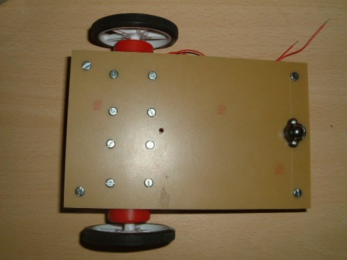
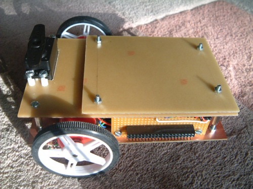
The motors and a roller were added first. The copper side of the board was mounted facing upwards as I was worried about possible reflections when line tracking that could cause errors. Originally, I was thinking about a four-wheel chassis with two drive motors connected via drive belts to the two free-wheels. This would give great stability and give tank-like steering. However, this hogs a lot of room and using a two-motor drive with a castor/roller would allow for more space for sensors. (compromise number one!).
Chassis Design
The lower chassis layer was where all the action is. Four pillars were mounted in each corner (using 3mm hardware) to allow the next layer in the sandwich to be added. The space between the boards was chosen to allow enough room for the motors and batteries to sit between the boards. 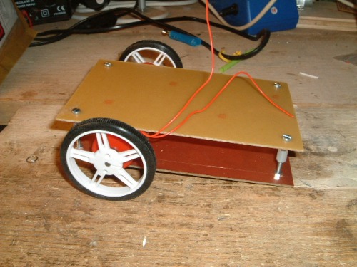
The Pluggable Interface
Next came the pluggable interface. I toyed with several types of connectors but needed a compromise between permanency and ease of reconfiguration. As this is a prototyping platform, any multi-pin plug/socket would limit versatility. The solution I chose in the end was to make a custom plug/socket using PCB headers mounted on veroboard, two rows of female sockets and one row of pins. The sockets can be used to interconnect via wires to the microcontroller - one pin at a time if necessary. The pins are mainly to attach test leads although a 20-pin plug could be added to bring all the data up from the lower board at once if necessary. I believe this gives a fairly flexible arrangement and with 20 pins, a lot of sensor data can be accommodated. The pluggable interface was brought out at the side of the chassis to give the maximum space on the lower deck and a short cable run up to the next deck.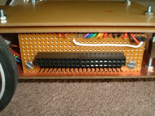
Light Detection (LDRs)
LDRs were mounted on small vero boards that were positioned at the front of the chassis, pointing forward. The connections were brought back to the connector.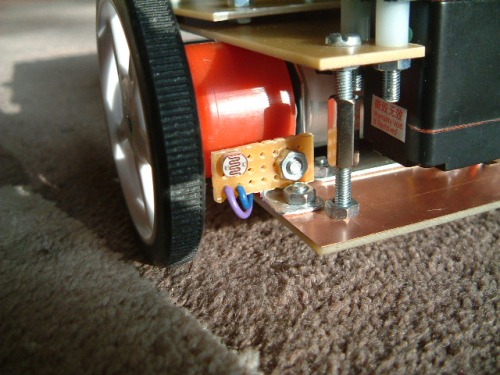
Line Tracking
The line-tracker modules were added to the lower deck and wires brought up to the interface. I decided to bring not only theoutput from the sensors to the interface, but also the power supply. This is because a IR transmitter module can draw up to 30mA and there will be a lot of them on this robot. The option is therefore available to turn the sensors on and off, be it via a plug in the interface, or through software control.![]()
Batteries and wiring loom
A battery compartment was added that contained 4 AA batteries. Although this is a clip-in box that allows for easy removal, I intend to add a socket so I can charge the batteries without the need to remove them. The wring from all the sensors was formed in a loom around the box to the interface board. Note there is an extra board mounted to the side of the battery box. This is used as a commoning-strip to allow the 5v and 0v feeds to be commoned where needed.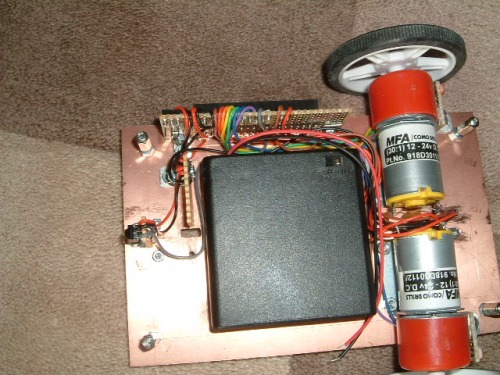
Charging and Power
The design is very modular and it is not onerous to remove the top-deck to change batteries but the time may come when there are lots of flying leads joining several decks together and dismantling the structure to change batteries may be inconvenient. I also needed to add a power on/off switch so it seemed sensible to combine the two. This uses a SPDT switch, that when 'on' will connect the battery to the robot and when off, will connect the battery to a power socket. The power socket can then be used to charge the batteries without being connected to the robot. The charging circuitry would be external to the robot (space limitations), but this is easily achieved by using a flying lead from a battery charger. The assembly was constructed on an aluminium bracket and mounted on the lower deck near the battery compartment. On day an autonomous charing station would be nice, but until that day is designed and built, a manual socket will do the job.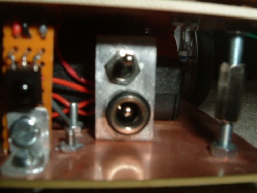
IR Receiver
An infra-red receiver was mounted centrally at the back of the robot. This was to allow some form of beacon to communicate with the machine. I have some plans for using a homing beacon to a recharging station that the robot could follow (in reverse) where it could then switch to line tracking to dock. It could also be used as a remote-control receiver to control the robot and put it into different modes. It's not on the immediate to-do list yet but it was wired up ready and the output brought out to the pluggable interface.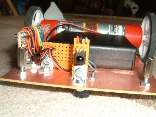
Servo Motor
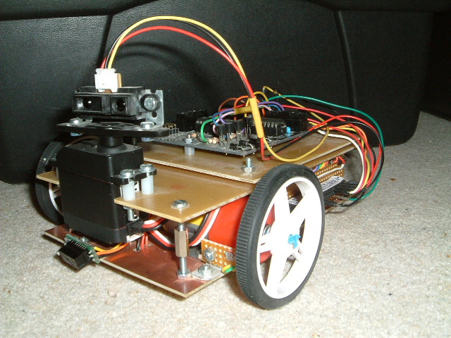
Now came the servo motor. This needed to be mounted at the front of the robot, have a degree of rotational freedom and will be the main sensor used for navigation. This is the only actuator (so far) that is not mounted on the lower deck. It is physically mounted to the deck above although most of the servo actually sits in the space between the boards. I could have used a smaller micro-server as it has a small load (a ligh IR pinger) but I thought that a heftier servo gave options for other things (such as a servo mounting a servo).
Note the space under the servo. This is where I intend to add a short-range edge-detector IR pinger. To the right is a space where the PIR sensor will go.
Servo Connection
The servo connection was plugged into a socket mounted behind the interface board and the control signal brought out to the interface. This allows the upper deck to be removed easily. I may put the socket on the upper board later if more sensors are used there, but for now all the sensors/actuators are brought out to the same interface connector.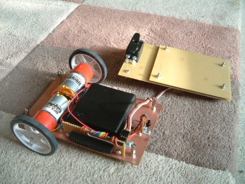
Microcontroller Mounting
Rather than mounting the microcontroller directly on the upper deck, I thought it would be more flexible to use a standard 'controller board' that could could be mounted above the deck on its own card. This would allow me to replace the controller board without turning the upper deck into swiss cheese with various mounting holes. So the bare board is shown below. I will make a few copies of this now so I have correctly sized and drilled boards suitable for various microcontrollers.
Note in this picture that there is space behind the servo to allow it to turn. Also, there is room above each wheel to add wheel encoder hardware which is an area I may wish to experiment with later.
Today, I finished the construction of the robotic hardware and am now ready to move onto putting a brain on the chassis and make it do something.
====================================================================================================
Microcontroller Selection
Having used the PIC16F690 on several projects, it looked to have many of the features needed for a small micropcontroller brain. However, I found a small microcontroller board (RKP18Motor) with a L273D H-Bridge on the same board but it required the use of an 18 pin PIC. This board was intended for use with a PIC AXE (Basic + bootloader) but I was sure I could modify it for my purpose.
I decided to use a PIC16F88 device as this had most of the functionality of the PIC16F690, but in an 18 pin package. This device has less I/O pins than the PIC16F690 and less Analogue inputs. It does support nanowatt technology although I am not sure if this will be of any use in this application.
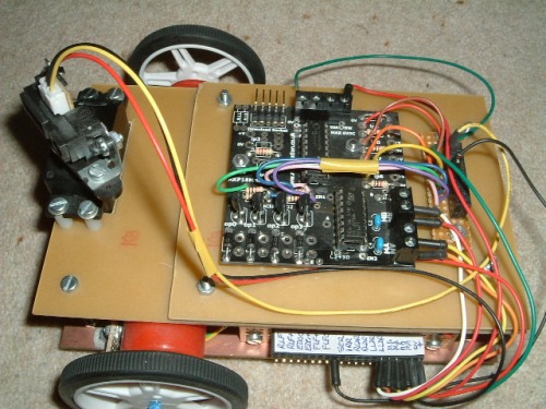
I have a PICKIT2 programmer so needed to modify the board to support ICSP and then set about running some test programs. It will make programming far easier to use C rather than assembler so I downloaded the HI-TEC C compiler for use with the MPLAB IDE. So this board was to be the brain of the robot. After modifying the board to use a header suitable for the PICKIT2, the board was mounted on a daughter-board that could be mounted on the upper deck of the chassis. A couple of header blocks we mounted adjacent to the board so that connections could be brought off the board for easy interconnection.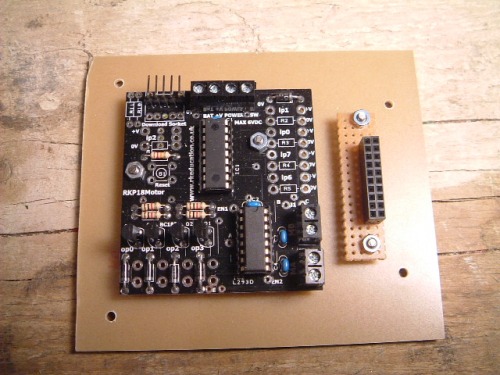
Microcontroller Board
The microcontroller board uses bits RB4-RB7 to drive the H-Bridge which is permanantly enabled. The 4 LSB of PORTB feed driver transistors. This suits well as PORTB can be used for output and PORTA for input. There are 7 multiplexed analogue inputs and PORTA contains 5 of these so that looks a reasonable use of resources. The PIC16F88 contains one hardware PWM so insufficient for motor speed control but it my prove useful for controlling the servo. The output is on PORTB.
Driving the Motors
The RKP microcontroller board contains an L293D H-Bridge. Motor direction can be accomplished by setting the inputs to the H-Bridge, two bits per motor. I wrote a simple motor-control library that controlled these bits (on PORTB) and wrapped them in higher level robotMovement API. The API does not allow for motor speed control but is sufficient for directional control.
Robot Movement API
void robotStop();
void robotForward();
void robotReverse();
void robotRightArc(unsigned char amount);
void robotLeftArc(unsigned char amount);
void robotRightSpin(unsigned char amount);
void robotLeftSpin(unsigned char amount);
A simple test program (motortest.c) was written to move the robot forward, backward, turn and spin in both directions. This was mainly to give some form of calibration and to see the underlying hardware was working as expected.
... and it works! As suspected, the 12 volt motors are rather underpowered, especially after going through the H-Bridge. The RKP board has a polarity protection diode in 5v line. I replaced this with a wire link to scavange some more volts and it is enough to allow the robot to maneuver gently around on a hard surface. On a table, it trundles around slowly with little noise but it will stall on a carpet. For testing this is fine, but I am concerned that if left to stall, the current consumption could destroy the H-Bridge. I decided to replace the motors with lower voltage equivalents. To keep the slow speed (as the low voltage motors will be operating at maximum speed, but 12V ones were not), the new motors have a 100:1 gear ratio rather than 30:1.
The new motors arrived today, 1.5-3v models although ok up to 6V. I did some testing using 3v and they move the robot about easily on carpet with lots of torque.They run a bit faster and more noisly than the previous motors but not overly so. The supply protection diode was replaced on the controller board so that the supply was brought down to 4.4v. The H-Bridge drops about 1.5v, so the motors will be powered at 2.9v - perfect.
Servo Control
Now the locomotion was understood, attention was turned to driving the servo. For this application, we are really only interested in looking left, looking right and looking straight ahead although the ability to turn to any position may be useful in the future. So the servo api should reduce simply to:
void servo_move(unsigned char how_much);
void servo_left();
void servo_centre();
void servo_right();
The last three functions would be nearly wrappers on servo_move(). The servo I received had no driver documentaion and a few searches on google revealed servo control to be a bit of a vague area. However it boils down broadly to:
- Supply 5v and 0v to the servo
- Send a PWM stream to the control input to move to the desired position
- The PWM stream has a 20ms period
- The pulse width ranges between 1ms to 2ms
Rather vague, and each servo type may vary slightly but overall it seems the period should be at least 20ms, but accurracy is not that important. 1.5ms seems to be the pulse width or 'centre' and 1ms and 2ms give -45 degress and +45 degrees respectively. Some servos have a greater range of movement so the PWM period can move outside the 1ms and 2ms limits, provided the servo physical endstops are not encountered.
The PIC16F88 has a hardware PWM which I thought would be useful for servo control. This uses TMR2 which (as yet) has not been assigned to anything else. However, running with a 4MHz clock, the longest period that can be set in 4ms, even when using the 16:1 prescaler. This is too fast for the servo so I looked to other means of generating the PWM stream.
It would be possible to generate the PWM stream with a purely software solution using delay loops. However, while in a busy-wait loop, the processor can do nothing else and 20ms is a long time to wait. As a compromise, TMR0 was used to generate the 20ms period and software used to create the pulse width which would mean a maximum of 2ms delay.
The servo control API was written using the interrupt service routine and a test program used to wrap it. I'm unsure at this stage how to decouple the API from the ISR so that the servoControl can move into its own library.
Well, the control of the servo worked as expected. For my servo, I found 1.65ms was centre and I could range from 0.9ms to 2.1ms when running some tests. I have hit a problem in the servo gets drivem fully counter-clockwise (hitting the end-stops) on startup or reboot. After many hours of head-scratching, this turned out to be a byte value overflowing on startup that manifested itself as a PWM burst with a very short pulse width. Now that is fixed, all looks to work fine.
Sensor Inputs
Basic locomotion and servo control was understood and implemented. Now was the time to start looking at some of the sensors and reading their values into the microcontroller. This will then allow programs to be written so that the
robot csn interact with its environment.
IR Range-Finder
The most important sensor to master was the IR range finder. This should be relatively easy to interface with as it produces an analogue output voltage proportional to the strength of the reflection it receives. This will be the first sensor I will tackle as this, combined with the servo and locomotion APIs will give me enough functionality to build a robot that autonomously finds its way around a room. That is my first goal and once that is achieved, I will see about adding the extra sensors as needed.
Ideally, it would be useful to pass the sensor values and robot state back to a computer (or LCD screen) to monitor what is going on. However, I will get the basics working and then work on reporting and telemetry although testing the IR sensor may prove difficult without it.
===================================================================================================
Software
I had decided at the outset to program the microcontroller in C rather than assembler. I feel to have 'done-my-time' with assembler and useful as it was to learn the hardware architecture, C allows the problem to be realized at the application level rather than at the register level. It is a long time since I programmed in C and it takes a while to mentally adjust from an OO language back to a hardware control language.
As each area is tested, the plan is to develop APIs which can be used later in more complex applications. I was originally going to package these as libraries but the HI-TEC C compiler will compile and link multiple C-source files without a problem which is more than suitable for my needs. After all, I just need a way of controlling complexity but am not intending to be a library writer! It may cause a little code-bloat but we will cross that bridge if we need to.
Initial tests seem fine, even using callback functions called from the interrupt service routine. With the movement and servo code split off into APIs and common headers, I'm starting to get enough building blocks to make something useful.
Analogue Sensor API
Many of the sensors used by the robot produce an output voltage that is proportional to the value being measured (be it IR-reflection, light etc). In order to read these analogue values, the PIC can be configured to enable the ADC, select the apropriate input and run an ADC conversion. The PIC16F88 can multiplex up to 7 analogue inputs although with the hardware board I am using, only 5 are really usable.
All ADC reads require a acquistion and settle time setup and each read will be similar except for the pin it reads. It therefore seems sensible to create an adc_read() API that can be used for all analogue sensors. i.e.
adc_read(unsigned char which)
It would then be possible to create simple wrapper functions for specific sensors. eg:
adc_read_ir()
adc_read_ldr_left()
adc_read_ldr_right()
The ADC can be setup as 10 bit, 8 bit and left or right justified. This can be done during PIC initialization or even using an API method although this may not be really worth the effort as we are getting close to the hardware here:
adc_setup(boolean left_justified, boolean ten_bits)
However, these are all niceities and I will flesh this out as we go. For now, I just want to get something working!
Testing and Integration
Reading the IR Pinger
The IR pinger was connected and a simple adc test program written where RA0 was used to read the the analogue output from the sensor. The digital output was sent to PORTB which fed an LED bar graph. Moving a hand back and forth in front of the sensor resulted in the bar graph beciming increasingly more illuminated the closer my hand got to the sensor. Incidentally, the maximum output was obtained when the reflection distance was about 2cm. Any closer than this and the sensor goes 'blind'. Objects could be detected up to 30-40cm away. This does show that if something is really close to the sensor, it will not see it so some kind of bump sensor will be necessary for this blind-spot
The IR Sensor was now mounted on the servo and the output leads modified so that could be plugged into rest of the development platform. Taking stock, we now have APIs to control movement and direction, turn the servo and read from the IR sensor mounted on the servo. Test programs had be written for each module in isolation, then movement and servo, so it was now time to wire all three together.
Hardware Matters
Up until this point, much of the hardware has been abstracted but now that several modules are to be used together, it is necessary to screw down particular pins for certain operations. Although an infinitely configurable system in nice in theory, dedicating certain pins simplifies the application software and allows for simple function calls to perform certain operations.
Function Type Port PIC pin Board I/O
IR Pinger (eyes) input RA0 17 ip0
Right Motor output RB4, RB5 10, 11 MB port
Left Motor output RB6, RB7 12, 13 MA port
Servo output RB0 6 R6 (op0)
This means that the adc_read_ir() function will always sample the analogue voltage on RA0. I can see going forward, that if a new microcontroller chip is used, new versions of the software will be required due to different pin configurations. There still seems lots of legs in the picf88, but if I upgrade to another processor later, I will make it a very large one and will probably stick with it for a while.
It was time to hardwire into the microcontroller I/O board. The relevant pins were wired to the adjacent connector board to allow them to be pluggable. For analogue inputs, it does mean the associated resistor may vary depending on the sensor. Initially, 4 of the 5 inputs were brought out to the microcontroller connector each having a 1k pulldown resistor. There is room for 4 outputs and a few of spare slots for power and ground. The output port (Port B) from the PIC was wired straight to the connector, leaving the driver transistors dangling. This meant teeing-off the board where necessary, direct from the microcontroller and left the driver transistors available for other usees. These will be connected as and when needed (for example up to LEDs, relay boards). However, for the initial goal, we only need one output (RB0) which is used to drive the servo. Since the main function of the robot will be to maneuver (4 bits) and move the servo (1 bit), the remaining Port B outputs (RB1-RB3) could be utilized as inputs if necessary although I beileve they may be better utilized turning power on and off to the various sensors via the driver transistors.
The final solution:
==================================================================================================
Integration
The software modules for locomotion, servo movement and IR pinger were put together to see how they co-existed. They did not like each other's company too well initially! Careful inspection showed that the servo movement API was overwriting the PORTB locomotion bits. A couple of late nights sorting this out and it was ready to go.
Initial Tests
The steering algorithm was very basic - go forward, and then look-and-avoid if necessary. The robot will turn towards a gap when comparing straight-ahead versus left and right. If there is no obvious gap, it will reverse and turn around. It works remarkably well and gets itself around most obstacles put before it. I have found the IR pinger to be very directional so it does not cover the corners of the robot. If something is straight-ahead, to the left or right, it will detect it. If it is offset by 4cm ahead, it may not. Also, a low obstacle below the line-of-sight will not be detected. However, generally it does a pretty good job and does not get stuck in corners although chair legs can be problematic.
I feel quite vindicated that I have achieved the goal I set out to do, building a small robotic platform that autonomously navigates its way around a room and the basic platform is extensible and has a lot more to be expored as yet!
Navigation Improvements
To improve the obstacle avoidance, a touch bumper switch could be added.This is a good catch-all mechanism, especially as the IR sensor goes 'blind' if too close to an object. Adding another servo to allow the main IR Pinger to have a second degree of freedom also gives much more flexibility. However, before
going down that road, it should be possible to use the existing sensors to improve performance.
Fixing the offset obstacle (where the front corners can hit an undetected barrier) could be fixed by moving the servo to scan the corners as well as straight, left and right. It will use more battery power to constantly be scanning while moving forward but this would hopefully detect obstacles before they become too close to detect. The servo movements while going forward will be small as it only needs to scan ahead, then over each front corner. If it detects anything 'ahead', it will then fall back to the existing avoidance mechanism. This change is just compenating for the tunnel vision of the IR sensor.
Scanning the low-level barriers could use the step-detector IR scanner although I suspect that that will be quite directional too.
Results
Scanning the sensor while moving has improved obstacle detection considerably. Another small change was rather than spin-left or spin right to avoid an obstacle, it reverses about 1cm before making the spin. This avoids situations where a wheel gets stuck (eg on a low-level obstacle) and the robot tries to turn around it. So now the robot seems to be able to navigate itself out of most situations other than a low-level bar that sits below the sensor height.
Another issue I have noticed is how battery life effects performance. When the batteries are fully charged, the robot does run faster. It also detects obstacles at a greater distance although due to the greater speed, it sometimes does not react in time. As the batteries run down, things are more predictabe. I put this down to doing all the optimizations when the batteries were not fully charged. I beleieve if I revist those optimization and rework them for full batteries, it will work ok with simi-discharged batteries, all be it somewhat more slowly.
Some Thoughts on Range Finding
Here are some thoughts on range finding that I will stick in the long-term todo list.
- It may benefit to not have the IR detector mounted right at the front of the robot. If it were further back, beam spread may mean it would be less directional so scanning the robot corners may not be necessary.
- An ultrasonic range detector will probably have a wider beam so may be a better option for general navigation.
- It may be that all 'radar' type range detectors have a blind-spot if too close to an obstacle. Bumper switches may be a necessary addition as eyes and ears can't be perfect.
- A range finder with a second degree of freedom may prove a good solution although will probably require considerable extra software support.
Primarily a Development Platform
- Actuators / output devices: one servo, 2xgeared motors
- Control method: autonomous
- CPU: PIC16F88
- Power source: 4 x AA NiMh cells
- Programming language: C
- Sensors / input devices: Sharp IR, 2 LDR, IR receiver
- Target environment: indoor on smooth surfaces