


Sandbot gets a Brain Transplant
The first incarnation of Sandbot seems to have yielded some successful results (see https://www.robotshop.com/letsmakerobots/node/30447). It can successfully navigate its way around a room and avoid obstacles along the way. The robot's mechanical structure is sound, there is plenty of motor torque and the design is modular enough to allow for easy expansion. It was implemented with a PIC16F88 and there is still a lot of mileage in that processor yet. Many thanks to those that offered good advice on ways to improve the design and I have tried to implement some of those suggestions and left appropriate hooks into the system where necessary. There were a few areas of the original design that are deficient, and I needed to plug these before moving forward, in particular:
- IR sensor directionality.
- Cater for IR sensor errors.
- PWM motor control and/or odometry
- Telemetry. Knowing what the robot is doing in real time.
- Experiment with Localization ad Mapping
IR Sensor Directionality
The IR sensor seems to very directional. I think an ultrasonic sensor is probably a better choice for general obstacle avoidance as it has a broader field of view. To overcome this directionality, the current design constantly scans left and right as it moves. I am hoping that by using an ultrasonic sonar (and by mounting it further back from the front of the robot), the scanning may not be necessary.
IR sensor errors
The IR sensor currently in use outputs an analogue voltage that is proportional to the distance to the object beng scanned. Although simple to interface, this does mean that surfaces with different reflectivity will give different echo amplitudes so can give rise to misleading results. Moving to a digital PWM/Timing pulse output should avoid some of these errors. It may also improve accuracy if several reading are made in succession and the modal or mean value is used.
Odometry and Motor Speed Control
Knowing where the robot is or where it has been is something I am keen to investigate. One way to achieve this is to count wheel rotations by using some form of encoder. This goes hand in hand with being able to control the speed of the motors (which the current design does not cater for) using a PWM mechanism. The PIC16F88 has only one hardware PWM module and uses a timer + software to create another for the servo. It would be very useful to have two PWM modules, one dedicated per wheel so each motor's speed can be individually controlled.
Telemetry
I find a lack of telemetry is the single biggest issue with the current design. Knowing exactly where in the software the robot is at any time will help in debugging and tuning of the software itself. The PIC16F88 has a built in UART which could be configured for this purpose. In an ideal world, if the telemetry was wireless, the robot could send data back to a console so it could be monitored remotely. I think this is much better solution than building a display onto the robot itself. An even better improvement would be if the telemetry link could be used for sending commands to the robot, either as a remote control mechanism or to switch the robot into different modes - duplex communication. Finally, the ability to remotely program the microcontroller could be useful although in a development environment, this is a convenience rather than a necessity.
Experiment with Localization ad Mapping
With the best will in the world, the robot is dumb. It is purely reactionary and has no memory or planning capability. I'm keen to pre-program the robot with a map of its environment so that it can make some more intelligent decisions during navigation. Identifying where it is on the map is an interesting problem and auto-update of the map based on what it finds during its travels is also challenging. I suppose the most difficult problem will be for the robot to have no map and no idea where it is and then for it to learn both as it travels. In order to experiment with these navigational concepts, I need to move away from the details of turning wheels, to software algoritms. I suspect, such solutions may require a considerable amount of RAM so I could hits the endstops with a purely micro-controller solution.
Microcontroller Modifications
The pic16f88 is quite capable of addressing many of these shortcomings although having two built-in hardware PWM modules would make speed control possible without the need to work around the problem in software. One timer is used for controlling the servo so this limits some of the hardware module usefulness. The chip contains a hardware UART that could be used for telemetry purposes although that would require some interfacing at the computer end.
Taking the above into account, although it would be possible to make the pic16f88 perform the tasks required, I think it will require a lot of effort and an easier solution would be to use a more powerful chip. There are several PIC processors available that could be used and also PICAXE and Arduino solutions.
The arduino solution looks interesting as it has many open source software libraries and the fixed form-factor that allows pluggable shields to be added looks a great idea. The arduino has its own IDE and a built-in serial monitor. The serial monitor gets me half way to my telemetry requirement, straight out of the box although the IDE seems to lack many of the powerful feature of the MPLAB IDE. Arduino compatible wireless modules are available that would make wireless telemetry a possibility, although they appear to be generic enough to be interfaced to a pic architecture easily. This seems an interesting solution so I have decided to park PICs for a while and dabble in the Arduino playground.
I believe the arduino, with its more sophisticated AVR microcontroller (well, one with more hardware modules suited to my purpose) will allow me to get to a position where it will be possible to experiment with localization and mapping although that depends on the data structures and memory available in the arduino programming language.
It is clear to me now that I should be aiming for a two 'processor' model, one which sits just above all the sensors and actuators and deals with the 'cortex' functions such as moving, object detection etc. A second 'cognitive processor' should be able to query and command the cortex processor to do its bidding over a defined interface. The cognitive processor will perform the higher-level mapping and localization functions and be more concerned with software algorithms, being abstracted from the underlying hardware. However, I need to walk before I can run, so this will have to wait for version 3 of the robot, although it's good to stick it in my head to know where I am heading in the long-term. If the arduino proves successful, it may be useful to keep it as the cortex processor and then to create another physical sandwich on the robot where I could use a much larger PIC processor to form the cognitive layer with lots of memory. It may be possible to use a mobile phone for the cognitive layer, but that is something to think about on another day!
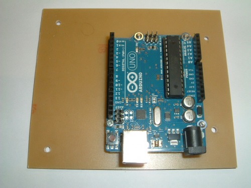
Arduino Uno
An arduino uno was my first step into the AVR microcontroller world. The hardware pins are more dedicated than my PIC design but there is a good variety of functionality, several PWM modules (for 'analogue output'), analogue inputs, digital I/O and a UART for serial I/O. The ide and programming language are very straightforward and the learning curve is considerably less than for a PIC. I tinkered with a few example programs and was amazed at how quickly you could get up and running. The serial monitor is fantastic, it should be possible to get some detailed debug data from the sensors using this so I can do a true comparison between IR and ultrasonic sensors.
Construction
There is no motor-driver chip on the arduino, so I bought a 'motor shield' kit that would plug into the arduino and provide this functionailty. I changed the headers so that another board could be plugged over the shield later (ideally a wireless board).
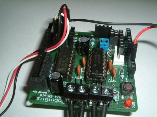
The sandbot was designed so it would be easy to swap out processor boards so I pre-drilled a new blank PCB card so it could replace the old one, and mounted the arduino on it. The arduino uno has a small footprint so I left some space next to it for a general-purpose breadboard/breakout board.
The arduino and motor shield were mounted and the new board put in place on the robot. Wires were connected to the motors and power and then it was time to hit the keyboard to perform some locomotion testing. Now that PWM is available, it should be possible to control the motor speed as well as duration of its on-period so hopefully I should get some extra functionality immediately.
Programming the Arduino
Well this was a revelation. The bundled libraries and simple environment make programming a painless process. I could reproduce all the functionality I had on the PIC platform within a couple of hours. This had taken me forever using a PIC. Admittedly I was writing the libraries themselves, and had thinking time to consider. However, there was no need to consult architecture diagrams, setup registers, flip bits, adjust timer dividers to get appropriate PWM clock-rates. My PIC libraries used interrupts and I note that my arduino code is not, so I assume this is being done in the libraries, just as mine were although the coding process seems more serial on arduino. There must be ways to add interrupts to arduino as I note two pins are dedicate to them but I will investigate this when I need to. Oddly enough, for the PIC system, I needed to know the chip architecture very well whereas the AVR architecture is totally hidden by the arduino APIs. I guess this is one step closer to dealing with navigation algorithms rather than bit flipping so I need to accept the abstraction and only dive into hardware when necessary.
Results
The serial monitor is brilliant, I'm not fumbling around in the dark any longer. I could get the robot to run motors, turn the servo, read from the IR sensor and all the results were fed back to the serial monitor to see what was going on. This made adjusting the IR sensor threshold levels much easier. However, I needed to suspend the robot wheels off the desk to prevent it wandering away. The USB cable tether needed to go, then I could get real-time logging back from the robot as it wanders around the room. So it was time to investigate wireless options. It would be great to be able to wirelessly program but I could live without that. Wireless telemetry is becoming an essential before I can move on. So that was the next task.
Going Wireless
I know I am treading well-worn paths here but sometimes you just need to work things out for yourself. It seemed to me there were three contenders for wireless telemetry, WIFI, bluetooth or RF.
WIFI is tempting option due to the high bandwidth and the fact I already have it in the house. However, WIFI modules for the arduino are expenive and it's a lot of technology considering I will be feeding it into a serial port at the robot end. I may revisit this option if I move up to a more powerful processor but the term overkill comes to mind here.
Bluetooth has a range of 10 metres or so which is more than enough for my needs. Again it is an expensive option and judging by the problems I have had with bluetooth with mice and compters, I don't have a lot of time for it. Maybe I'll come back to this in the future.
Custom RF is a cheaper option and the lower data-rate fits better with my simple requirements. I see Xbee and Zigbee are simple options and have a range similar to WIFI. After consulting with google for a while, it looked like Xbee was the way to go, a Xbee shields exist for the arduino. So this is my preferred option and I may grow into wifi at a later stage.
Configuring Xbee
I bought a couple of Xbee modules, a USB->Xbee adaptor (PC side) and an Xbee shield for the arduino. There seem to be a confusing array of Xbee modules of various power ranges and those suitable for mesh networks. I went for simple point-to-point as that is all that is needed here. There is a configuration program called X-CTU for the xbee which is free to download. Unfortunately, this is windows only but can be run in a VirtualMachine on a Mac with no problems. I'm not really very familiar with windows and soon ended up looking for drivers but the internet is a wonderful thing :-). There are the steps I took to configure each Xbee:
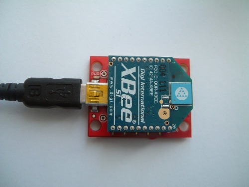
- Connect Xbee to PC via the adaptor board
- Install driver so PC recognizes the adaptor
- Connect to Xbee using X-CTU using 8 bits, no parity, 1 stop bit at 9600 bps
- Set communication speed to 57600 bps
- Set PANID = 4444
One Xbee was used in the shield and the Xbee board sandwiched onto the arduino stack. The other was left in the adaptor and plugged into the USB port of the PC. I am aiming at making the wireless connection transparent so that the computer is unaware that there is not a cable between it and the robot. It took some time fiddling around with drivers for the adaptor (fdti chip) but once those were sorted, it worked fine.
I used an IR-pinger test program to send measurements back via the serial interface and the output comes through on the arduino monitor, totally transparently - Xbees are great :-). I did some simple range tests and the telemetry worked fine over a 6 metre range which is more than I need so am very pleased with the outcome. It was also possible to send the data back to the computer and display it in the terminal using 'screen'.
Out of curiosity, I tried pushing the data rate up to 115200 bps, the maximum the Xbee will support. Although this worked, I noticed that occassionally (about 5% of the time), I read back junk. I assume this is a sync problem and bits were being dropped. With motors and servos running, the robot will be an electrically noisy environment so I think 115200 bps is too high for the data rate, I'd rather have it running slower but more reliably. I returned the data rate to 57600 bps and found I had no telemetry errors at all, even when running over a long period of time.
Xbee Limitations
As expected, I could not program the arduino remotely but then I found a problem. If I try to program via the USB cable, it does not work either. I believe there is bun-fight over the Tx and Rx pins as the Xbee shield is trying to use them at the same time as the USB lead. There is a small switch on the Xbee shield that allows the xbee to be disconnected and USB programming works as before.
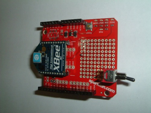
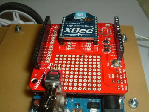
Modifying the Xbee Shield
The Xbee shield I use comes from sparkfun. It has a small DPDT switch that allows the DOUT and DIN pins on the Xbee to be switched to Rx,Tx or D2,D3 on the arduino. This is a small surface-mount switch which is hard to get at once the shield is put into the arduino stack. There is a small prototyping area on the board and I reasoned I could mount a minature toggle switch here and replace the one on the board. Getting the small switch off the board with a heated spade proved tricky and I could not use the original solder pads but luckily there are enough places on the board from which to pull the appropriate signal. The result is shown below. The switch sits just above the USB port and is flipped one way for USB programming, then the other for wireless operation.
Using the SRF05 ultrasonic Sensor
This is used in mode 2, where one digital pin is used for transmit and receive. It is simple to convert the delayed echo time to distance and this was done to make telemetry readings clearer. The IR pinger was replaced on the robot with the SRF05 (also mounting it further back from the front of the machine) and some simple tests undertaken.
Static testing proves the ultrasonic sensor to be considerably better than its IR counterpart. Distance can be measured accurately, the beam-spread is wider and even narrow items (eg a pen) can be detected without too much difficulty. From limited tests, it also appears to be less affected by the material the soundwaves are being reflected from. Time will tell how accurate it really is in the presence of motor and servo noise, but results look really encouraging.
Integration Testing
Once all the boards had been tested in isolation, they were all plugged together into the arduino stack and everything wired together. I had peppered the motor shield with female header blocks to give a lot of interface points, which frees the pluggable interface from becoming overcrowded with wires.
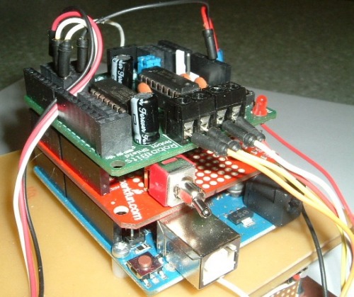
Making all the modules worked together was not quite so straightforward. It appears that the Motor Shield I am using uses pins 9 and 10 which are also used by the Servo library. They fight over an AVR timer so it is not possible to use speed control while using the servo. This is not a train-smash as speed control is not high on my hit-list. I could rewire the motor board to use different PWM pins but provided the motor direction can be controlled, I'm not too bothered.
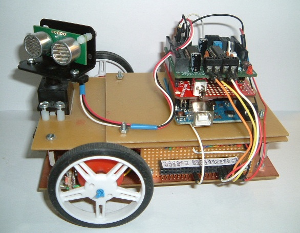
Locomation, servo control and Ultrasonic detection were all integrated and the arduino was programmed accordingly. Flipping the program/wireless switch and I should be able to monitor exactly what the sandbot is doing as it moves around the room. And it works :-). The development-test cycle is much faster with the wireless telemetry. The completed robot with its new brain and sensor are shown below
Conclusions
I can conclude that the brain transplant has been sucessfull as it has the same or better functionality as the previous version, but with the addition of remote telemetry and and improved distance sensor. I will experiment with some of the other sensors for a while before moving onto the area of localization and planning. The modularity and availability of pluggable sheilds make the development process much faster although it comes at a cost. Firstly, the abstraction from the hardware layer means you are not fully in control of the underlying processor. Secondly, the arduino route is more costly than raw PICs, but this is th price to pay for the modularity and large array of compatible hardware.
Now there is a wireless link, I may experiment with moving the cognitive functions completely off the robot and into the PC. Sensors could collect data and send it to the computer which would crunch the numbers and send locomation commands back to the robot. However, that is a job for another day!
object avoidance using ultrasound
- Actuators / output devices: DC motors + one servo
- Control method: autonomous
- CPU: Arduino Uno (atmega328)
- Sensors / input devices: SRF05 Ultra Sound
- Target environment: indoor