


RS4 - Self balancing Raspberry Pi image processing Robot
RS4 Robot
** Update 15-11-2013 **
Added line following feature using camera. See last video.
** Update 29-10-2013 **
New video with some more symbols to read. This is the last update with these features, now I'll work in some improvements and new features to implement. Hope you like, thanks for all your comments.
** Update 23-10-2013 **
New video.
The robot is now using the ultrasonic sensor to avoid collisions. Have introduced some more symbols that the robot can read, in this video I'm using only the "turn around" and the "stop". Hope you like, best regards :)
** Update 17-10-2013 **
I’ve been working on the robot and I have some new updates to share. I’m learning how to use OpenCV and know I’m able to do some more complex image processing than simple color tracking. RS4 now can detect and read some symbols and perform associated actions. In this new video it follows and reads the ball symbol meaning that it must search and follow the ball.
Hope you like, just a short video and the robot needs some more tuning. I will include more symbols and actions then I’ll post a longer video
***
Hello,
Here is the robot that I'm working on, you can see the latest video here on the right, although it suffered some modifications since then.
I'll divide this description in topics as it's easier for me to describe it this way. The idea to build this robot came from buying a Raspberry Pi, when I saw it I said "I've got to build a robot with this " :) . I have built other robots in the past but this one is the most complex and the first with image processing. (Sorry for any English errors, it is not my native language).
Chassis
The robot chassis was designed by me, I used a 3D tool to generate some previews mainly because I needed to have an idea of the size and components distribution before build it. Here you can see the model of the robot:
After this I began the building process, I bought a carbon fiber plate (more or less the size of a A4 sheet) and cut all the pieces by hand with a mini drill machine (unfortunately I don't have a CNC machine to do this job). I bought some aluminum profiles to make spacers and fixing parts as you can see in the next photo. The result is a very light and strong chassis.
· Motors and wheels
I'm using stepper motors in this robot, no special reason for that. I bought them as Nema 17 motors, the motors reference is LDO-42STH38-1684A 121121 LDO MOTORS. These type of motors have a nice robust look and are usually used in CNC and RepRap machines.
The wheels are from a RC 1/8 Buggy, you can find it easily in any RC store as they are standard size. What I like the most in this wheels is their soft touch, this way they work as a damper for small obstacles allowing smooth run.
To connect the wheels to the motors I used Traxxas Revo hubs and nuts like showed in the photo, these are the only ones that I found with a 5 mm hole, the same as the motors shaft. This way is more or less plug and play.
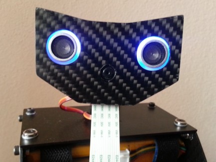
· Head
For pan and tilt I use 2 micro servos (Tower Pro MG90S), very cheap and easy to get. The head has a holder for the Raspberry Pi camera module, a ultrasonic sensor and 2 RGB LEDs.
You can see some details of the robot in the next photos
Balancing and motor control Board
This robot uses a dedicated board for balancing and motor control (I want to use Raspberry Pi only for high level tasks). This board is my design and it uses the following components:
- 2 L298 + 2 L297 stepper motor drivers, (yes, I know they are old but they are cheap and easy to find to, in a future revision I'll use something from this century :) );
- Murata ENC-03 Gyroscope, analog single axis gyro, very easy to use;
- MMA7361L Accelerometer, 3 axis analog accelerometer (I use a module, this chip is to small to hand soldering);
- PIC24FJ64GA002 microcontroller
It allows I2C and serial communication. Photo of the board and the motors here:
Servo control board
I'm using a modified motor board to control two servos and to read the ultrasonic sensor (not yet being used). This is a temporary solution, I intend to design a dedicated servo control board or buy one.
Power
The energy to power the robot comes from a 2000 mAh LiPo 3S battery. To generate required voltages I'm using one 3.3V regulator and two 5V switched regulators. I want to design a dedicated power board in a future revision.
Balancing control
· PID
Balancing control is performed by a PID cascade, like showed in the next picture. This way is possible to balance the robot even if you move the center mass or run it in a ramp. It will find a new balance angle that allows it to be balanced and stopped. In fact both the controller are PI only, the derivative gain is set to 0 because it causes the robot to shake even with small gain.
PID implementation is as simple as this:
pTerm = Kp * error;
sum += error;
iTerm = Ki * sum*Ts;
dTerm = Kd * (error - lastError) / Ts;
Cn = pTerm + iTerm + dTerm;
lastError = error;
For PID tuning I used a Bluetooth module which allows me to adjust Kp,Ki,Kd for both the controller in real time. This way you can immediately view the effects and reach the desired behavior for the robot. In this video you can see it successfully balanced for the first time .
https://www.youtube.com/watch?v=B3LmcVQaF6Q
· Sensor fusion
Sensor fusion (gyroscope + accelerometer to get the leaning angle) is performed by a Kalman filter, not much to say about it, it works really well. Follow this fantastic tutorial, here is everything you need to know, includes explanation and implementation.
http://blog.tkjelectronics.dk/2012/09/a-practical-approach-to-kalman-filter-and-how-to-implement-it/
· Motion control
OK, the robot is balanced but now it is necessary to move it. Moving forward an back is quite easy with this PID cascade setup, you just have to give a set point to the first controller and it will calculate the appropriate leaning angle to reach that speed. Something like this:
setAngle = calcCn1(instSpeed - setSpeed);
instSpeed= calcCn2(angle - setAngle);
To turn the robot I'm attenuating the speed in one wheel, depending on the side it needs to turn. This way the robot keeps the balance as both wheels are reflecting the control system speed. Implementation looks like this:
instSpeedL = instSpeedR = instSpeed;
motorSpeedL(instSpeedL * factorL);
motorSpeedR(instSpeedL * factorR);
0 ≤ factorL ≤ 1, 0 ≤ factorR ≤ 1
To perform spins, rotating in turn of itself, what I do is to give an opposite offset speed to the wheels. With the wheels rotating symmetric speeds it will perform a spin and stays balanced, completing the implementation it will look like this:
motorSpeedL(instSpeedL * factorL + spinSpeed);
motorSpeedR(instSpeedL * factorR - spinSpeed);
If spinSpeed is positive the robot will spin clockwise, other way it will spin counter clockwise.
That’s the way I found to control the robot motion, there are possibly other methods. Other important thing is that with stepper motors you shouldn't apply big speed changes abruptly or they will slip, this can be solved with some low pass filter applied to factorL/R and spinSpeed. This way works well in my robot. In this video you can see the a run with Bluetooth control, it can run faster than this but will easily fall if it finds some small bumps on the road.
https://www.youtube.com/watch?v=YLNWpxRAM1Y
Raspberry Pi
I'm using a Raspberry Pi model B 256 MB with a micro SD adapter because of the limited space on the robot. I have a small WiFi adapter but the robot is not yet using it. The installed operating system is Raspbian, I managed to get OpenCV working with the Camera module thanks to this tutorial, great stuff here:
http://thinkrpi.wordpress.com/2013/05/22/opencv-and-camera-board-csi/
At the moment I'm using serial communication between the Raspberry and the motor board and servo control board but I intend to use I2C as it is a more appropriated method. The reason I'm using serial now is because the interface code was already done for the Bluetooth module (it is a cheap serial Bluetooth module). I have to spend some time working in the I2C interface.
Serial interface with the Raspberry is quite easy, you just have to disable terminal emulation. I'm using WiringPi library to achieve serial communication and to control Pi's GPIOS without any issues.
Image processing
I have very little experience with image processing, it is the first time I'm using OpenCV and I'm still learning how to use it. My first example is the object tracking (ball) by color filtering like in this tutorial:
http://www.youtube.com/watch?v=bSeFrPrqZ2A
It works well but is sensitive to lightning changes, at this moment I'm using YCrCb color space instead of the HSV but the results are similar. With the object coordinates in the screen I control the servos to point the camera to the object and control the robot direction based on the head angle.
The ball following was the first simple example to integrate all the parts of the robot, the robot behavior was funny and I decided to publish the video on youtube.
Final remarks
This robot is an ongoing project, I'm continuously building new parts and modifying others. I don't have a defined goal for this robot, I would like to give it some autonomous navigating capabilities. It has some real potential I just have to work on image processing and learn some more technics. I intend to add a speaker too.
In the initial robot sketch it has 2 arms, it would look cool but it gives a lot of work to build and I'm aware that is hard to give it some useful function like grabbing objects or something. I could use arms to get the robot back on balance after a fall, maybe in a future update.
I have implemented odometry in this robot, at the moment I'm not using it. A 3 axis gyro would be very useful to correct odometry angle errors, a point to review in future revision.
Hope you like it, I will try to keep this post updated.
Best regards to all robot enthusiasts :)
Samuel Matos
- Actuators / output devices: 2 servos, 2 Stepper Motors
- Control method: autonomous, Bluetooth
- CPU: Microchip PIC, Raspberry Pi ARM
- Operating system: Linux(Raspbian)
- Power source: Lipo 3S 2000 mAh
- Programming language: C++, C
- Sensors / input devices: HC-SR04, MMA7361 Accelerometer, Raspberry Pi camera module, Murata ENC-03 gyro
- Target environment: indoor