


Rover infinity 1.0
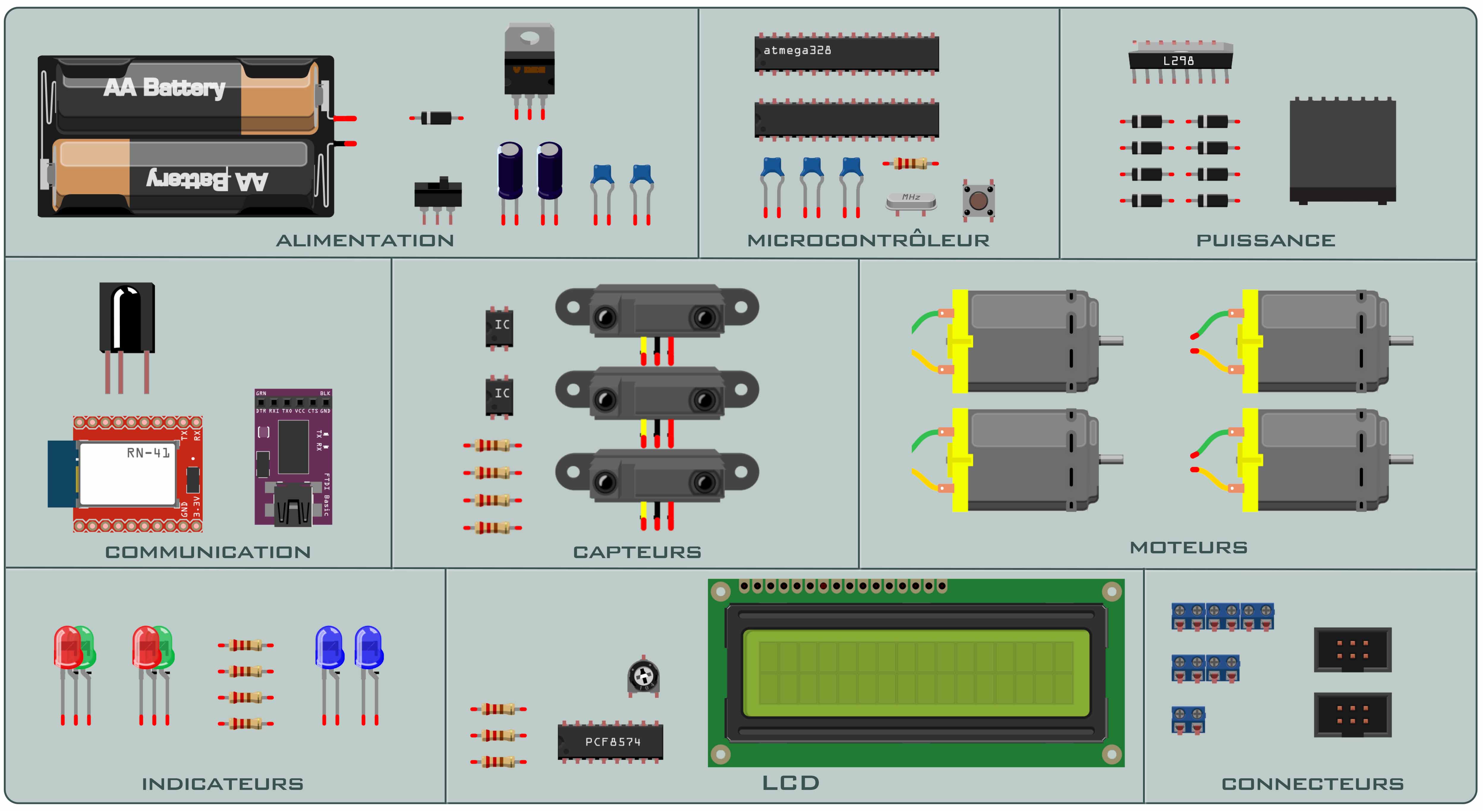
— Composants list —
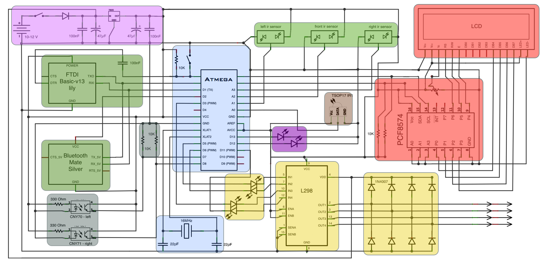
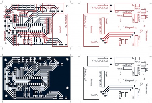
— Global schema —
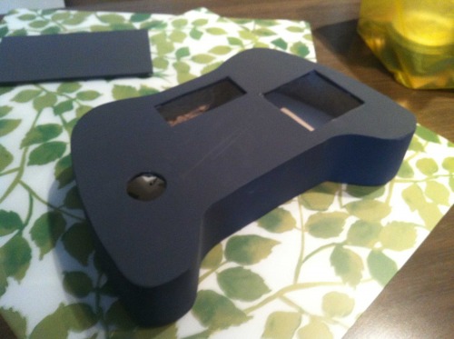
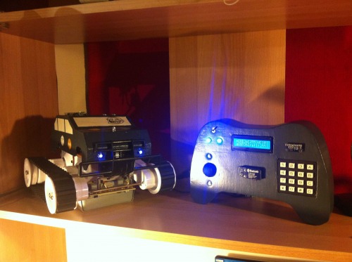
— Result —
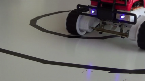
— Line Followr mode —
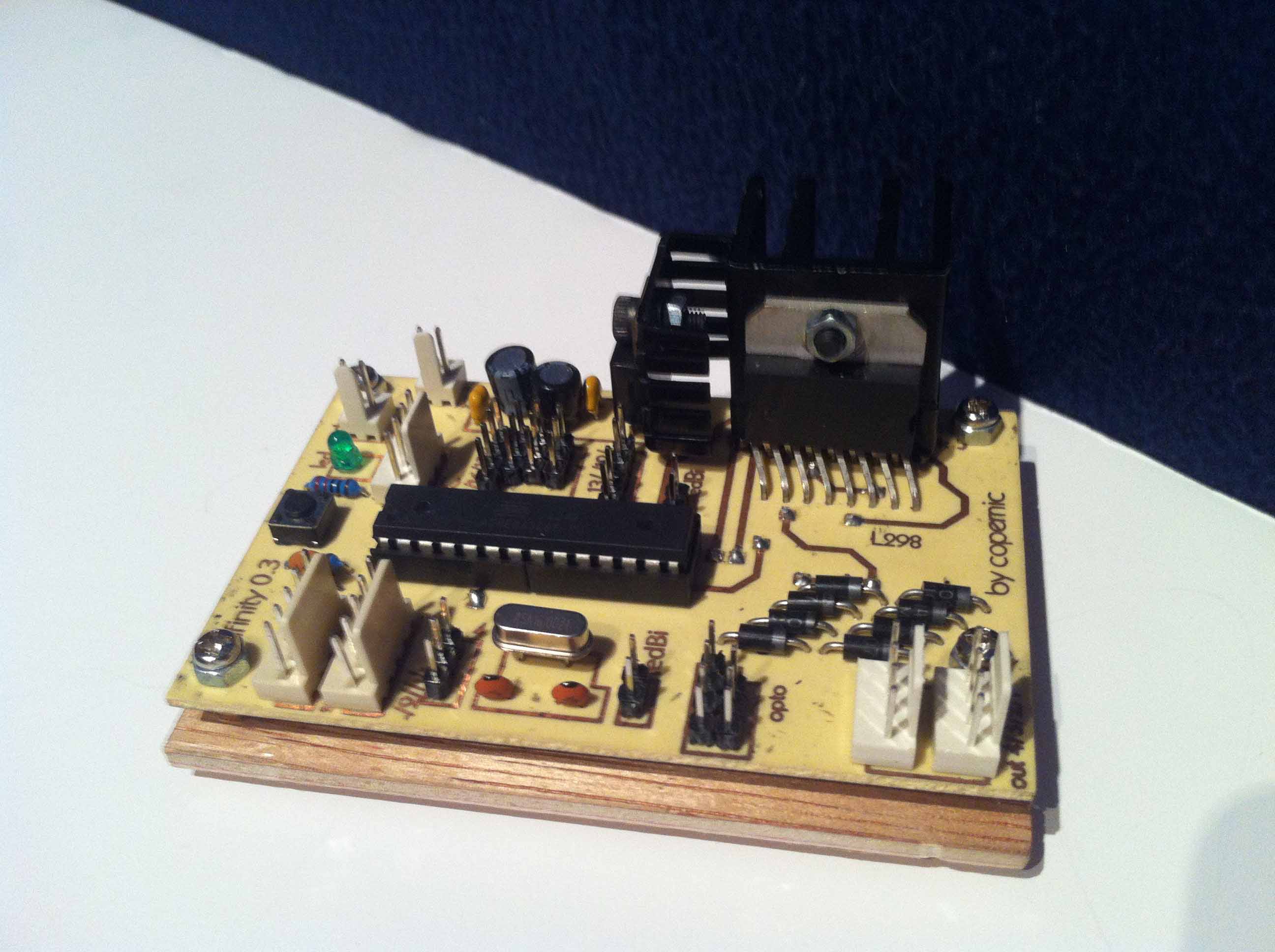
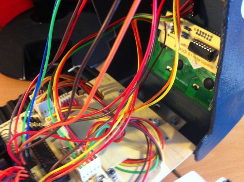
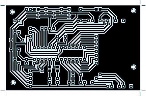
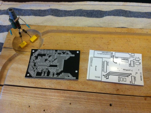
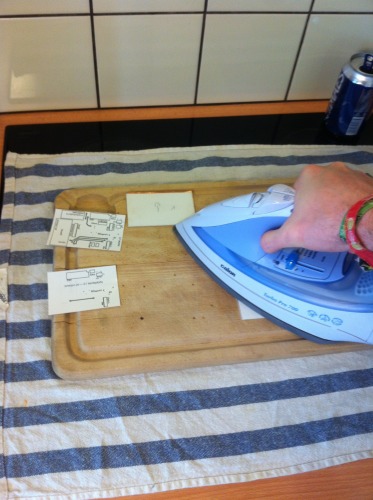
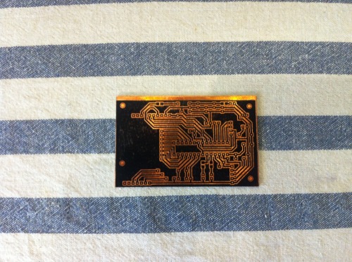
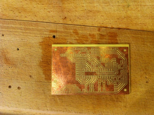
— 'homemade' PCB —
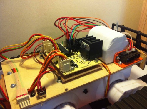
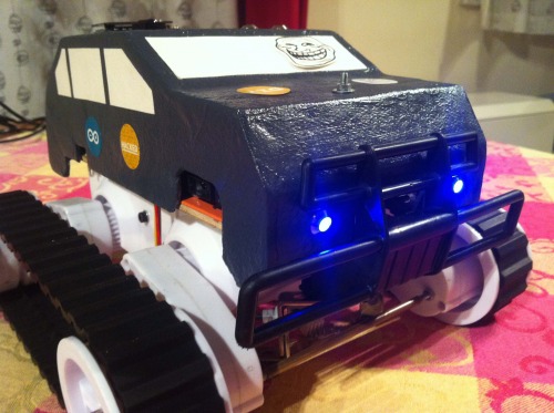
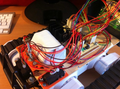
— Rover —
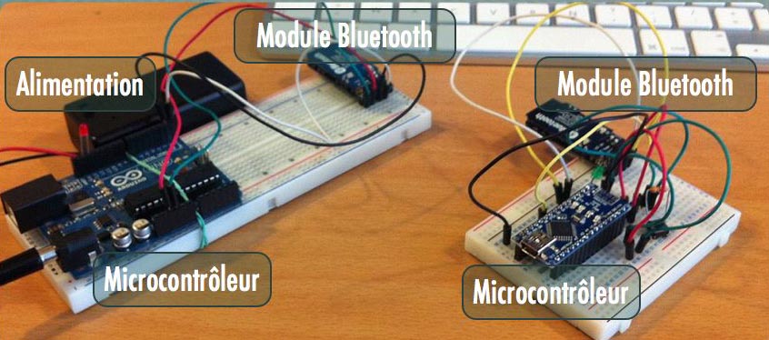
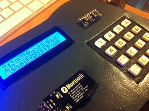
— Bluetooth modules —
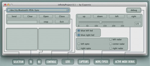
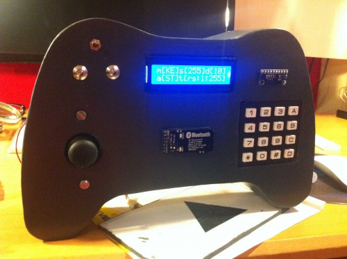
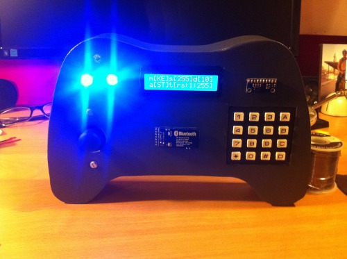
— Graphic interface —
— Rover —
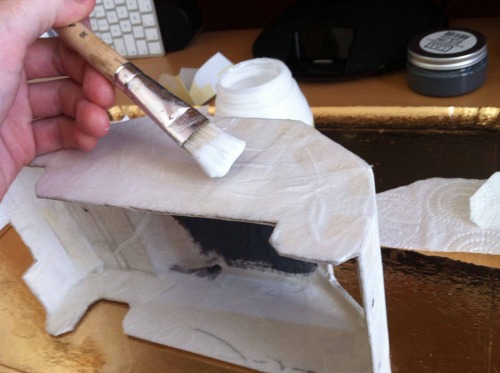
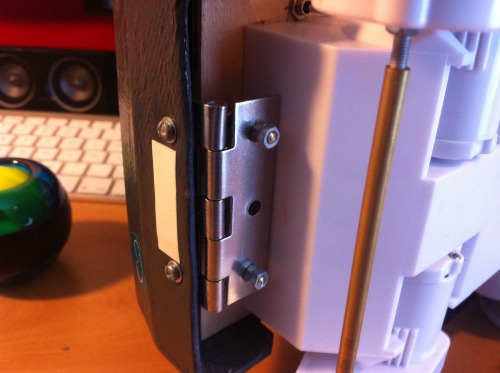
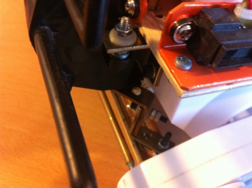
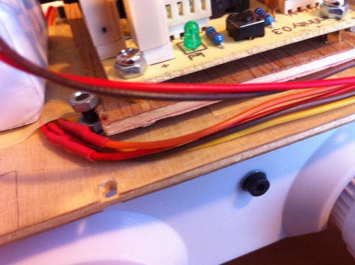
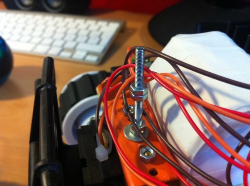
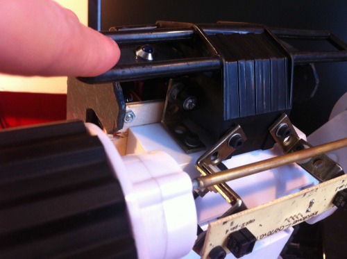
MORE PICTURES
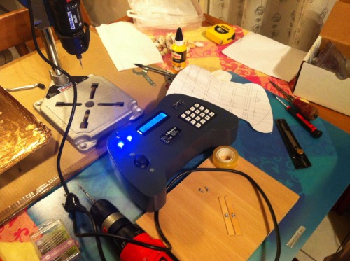
UPDATE: WORK IN PROGRESS — TELECOMMANDE (JOYSTICK, CLAVIER & ACCELEROMETRE)
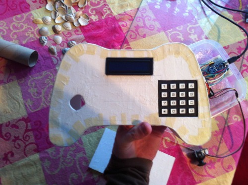
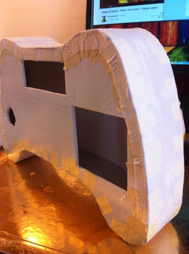
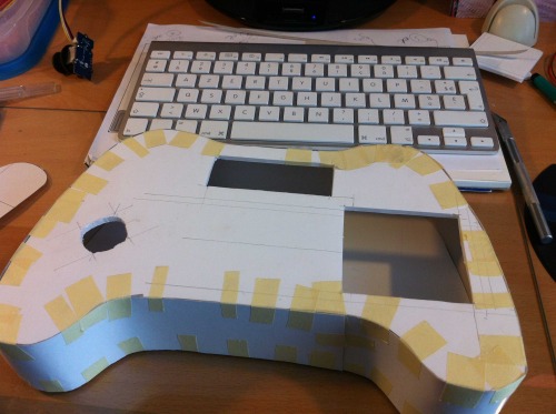
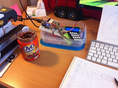
UPDATE — TELECOMMANDE (JOYSTICK, CLAVIER & ACCELEROMETRE)

UPDATE (2013|11|15)
PCB — RS232 REMOTE CONTROL

NEXT STEP: VIDEOS
More to: www.leblogdecopernic.net
Rover infinity 1.0
- Control method: undefined
- Operating system: undefined
- Power source: 9.6V 1500 mA/h
- Programming language: C++ (Arduino)
- Sensors / input devices: IR, Optocoupleurs
- Target environment: Indoor or outdoor