


Rocket Brand Studios Tadpole Spurt Shadow Runner
Well, Chris the Carpenter has been hard at work since MakerFaire perfecting a design for a robot kit that can do... anything. Well, almost anything. OK, a lot of things. Cool things that we usually ask basic robots to do. He calls it the Tadpole, and it is very neat.
I'm working with Chris to create some designs that operate without a microcontroller, Inspired by the SpurtBot designs from Rostock University and my own work in this area.
Here's the third one, based on the Tadpole Educational model, with the Spurt add-on to the chassis to allow the solderless breadboard to be extended in front of the robot and inverted so sensors can point to the floor.
<INSERT PIC OF ROBOT>
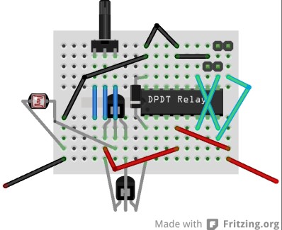
In the breadboard layout below, the two 2-pin headers at the top corners are for connection to the motors. The right header is for the right motor; the left header is for the left motor. If either motors spins backwards, simply disconnect if from the header and reverse the connection by swapping the two wires. The battery connections are the black and red wires at the bottom corners.
Above: Fritzing Breadboard Layout
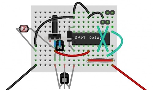
Here's the schematic for the circuit I came up with.

(click for larger image)
The photo resistor controls both motors through the relay. As long as there is enough light, both motors drive forwards. If the robot runs into a shadow, the left motor should spin full time when the battery is connected. Its speed is reduced by passing the positive battery connection through four 1N4004 diodes, dropping the voltage. The resulting loss of speed will enable to right motor to turn faster than the left when it is turned on by the sensor. The right motor is controlled by the sensor. It should only spin when the sensor detects a reflection. The NPN transistor is triggered by the sensor, which then allows a connection from the right motor to ground. When the right motor is activiated, it will run faster than the left and keep the robot turning in towards the line.
Component List:
- (2) BC337 NPN transistors
- (1) DPDT non-latching relay (Shinmei RSB-5-S, Jameco Part #139977 used here)
- (1) 1N4004 or similar diode
- (1) Light Dependent Resistor (LDR) (Jameco Part #202403, 200k Ohm in dark)
- (1) 10k Ohm potentiometer (Jameco Part #2118791 used here)
- (2) 2-pin male-male headers for connecting motor leads to breadboard
- (2) 1-pin male-male headers for connecting power and ground
- Some solid core hook up wire for making connections on the breadboard
Other Versions:
Runs from the shadows
- Actuators / output devices: 2 DAGU Little Black Duck servos factory modified to be gear motors
- Control method: Simple BEAM like circuit
- Power source: 4xAAA alkaline batteries
- Sensors / input devices: Two LDRs
- Target environment: indoors