


Robutt Number Two
This is my second attempt at a robot, and my first more or less blind since I basically followed the start here tutorial for my first one. My goals here were fairly simple, I wanted to utilize some more accurate and substantial tools than just the Sharp IR detector, make the thing a little faster by utilizing a separate power supply for the motors and hopefully learn a thing or two.
I picked up everything from Solarbotics this time, because I really like their site and their shipping is always two days ahead of schedule. I bought some treads, new motors (GM9 instead of GM3), their compact L298 motor driver and a few other random components (LSR, line detector sensors, some fancy LEDs). As I mentioned previously I am not really a circuitry/electronics guy and the first robot was my first time playing with circuits (aside from building a PC) and it was my first time soldering as well!
So, as you might expect I am kind of crappy at soldering, so I mention this as a warning to all new solderers like me: solder all the way! Doing it halfway doesn't really work properly, as I found out. My driver board was really flaky and the right tread was in constant motion when it wasn't being fed any input, which is obviously wrong. It took me a while to even figure out what was wrong, but once I took everything apart and re-soldered the entire board everything started working properly. So yeah, I'm sure this is amazingly obvious to all the regulars here, but it's super important to actually do it right. Don't cut corners for no reason!
After a lot of manual consulting and looking stuff up and soldering and scratching my head I finally got the motor driver connected to the Picaxe and turning those wheels properly. The first video is my first test run where it's basically just running through a list of navigation commands. I know this is probably fairly basic stuff, but it was very exciting for me!
June 2, 2010
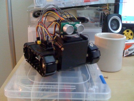
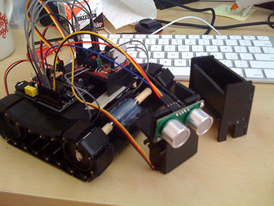
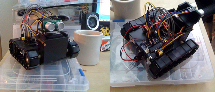
Hooking up the SRF05 turned out to be easier than I expected and the servo was easy of course. At this stage he just kind of pokes around on the floor, avoiding obstacles and deciding where to go. Nothing very exciting but at least there's some level of autonomy now, and the SRF05 works a million times better than the Sharp ever did.
I will say that not planning out the build has kind of bit me in the butt. The two boards don't really fit together in a useful way and he's held together by masking tape.
June 6, 2010
Okay being held together by masking tape the body was giving me issues as far as stability went. It wasn't horrible, but the complete lack of planning and the tape not making the build as solid as it could have been made it frustrating at times. So this morning I embarked upon a full disassembly and rebuild using my newly acquired hot glue gun! Don't leave home without it, kids.
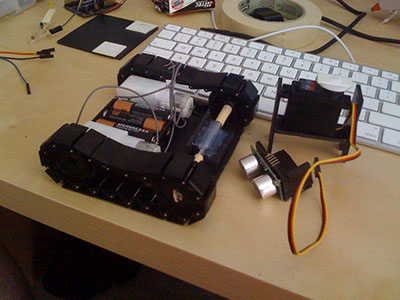
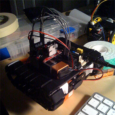
The body consists of two 'plates' which are held apart entirely by the motors. In the front you can see a big mess of glue and bits of plastic that hold the front axle (a radio antenna in its former life) in place. To the right is a compartment I built that houses the main (and currently only) servo. The point of that apparatus was for easy disassembly of the robot. The original body had the servo taped into place and it was a pain in the ass to actually move it or reposition it because I had to peel off all the tape and then re-tape everything. So yeah. I also made a little bracket for the SR05 though that's only held onto the servo by some double-sided foam tape.
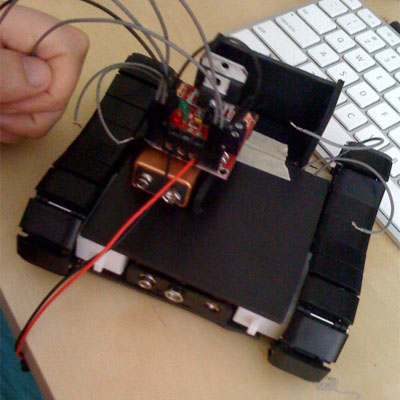
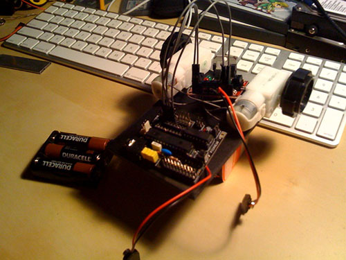
The next issue I had with the build was that the motor driver and picaxe could not comfortably sit on the top plate together. It's actually precisely the same width as both of them next to each other, but that creates issues with the treads. My solution was to elevate the motor driver. This lets the picaxe sit slightly below it and I can also put the 9V used to power the motors (and motor driver) under it. The picaxe board fits perfectly next to the 9V!
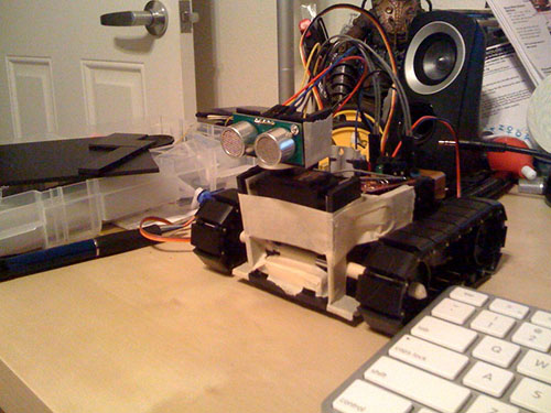
This is just the finished servo holder thingy. Nothing fancy, but it does the trick and the fit over the axle (you can see the notches) is tight enough that it needs no additional adhesive.
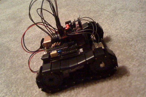
The finished product! Well, not quite since the treads were a little droopy so I fixed those up, but this is basically the final product. Right now he only drives around and avoids obstacles and turns on his light when it's dark. I'm going to see what I can do to make it a little more interesting though and provide a new video. I also have some line follower dealies so I can make him detect that he shouldn't fall off a table. The possibilities are endless!
drive around
- Control method: autonomous
- CPU: Picaxe 28x1
- Power source: 3AA cells for logic circuits, 9V battery for motors
- Programming language: Picaxe basic
- Sensors / input devices: SRF05, one LDR
- Target environment: indoors