


Robot Delta
[Update October 17, 2010] Preliminary videos added.
[Update October 24, 2010] Robot Rally video added.
I found several limitations with Robot Charlie, so I created a new platform to continue development and hopefully enter the Polyathlon competition which is organized by the Atlanta Hobby Robot Club. The biggest difference from Charlie to Delta is abandoning the continuous rotation servos I've been using for the drive train and going to BaneBots gearmotors.

Hardware
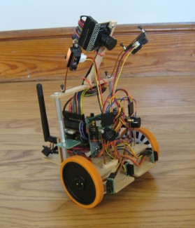
The main controller is the SRV-1 Blackfin Camera from Surveyor Corporation. I am also using their Radio/Motor control module for Wifi connectivity and H-bridge control of the motors. This module incorporates a Lantronix Matchport WLAN 802.11g radio, Fairchild FAN8200 dual H-bridge, and 3.3V switching regulator.
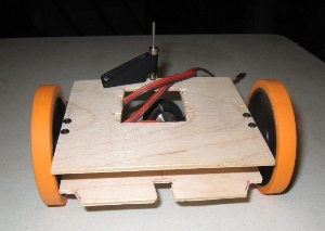
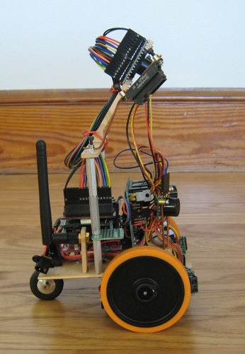
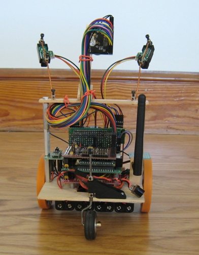
The structural chassis is made from 1/8" light plywood, commonly used in the construction of RC model airplanes. The drive train components on Robot Delta are:
- BaneBots 2-7/8" wheels
- BaneBots FF-050, 118:1 gearmotors
- BaneBots Hex hubs
- BaneBots 16mm motor mounts
- Dubro Tail Wheel Bracket, 0.60 size
- Dubro Tail Wheel, 1-1/4"
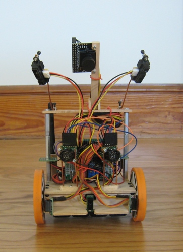
The sensors on Robot Delta are:
- 2x Maxbotix LV-EZ1 Ultrasonic Distance sensor
- 3x Sharp GP2Y0D810Z0F Infrared Digital Distance sensor, 10cm range
- 2x Sharp GP2Y0A21YK Infrared Analog Distance sensor (for table edge, drop-off detection)
- 4x Fairchild QRE1113GR Infrared Reflectance sensor (quadrature wheel encoders)
- 1x Omnivision OV7725 VGA camera
Other components used:
- 8x Tenergy NiMH AAA 1000mA batteries
- 1x hexTronik UBEC 6V/3A battery regulator for motor power
- 1x LM7805 5V/1A Voltage regulator for 5V sensors
- 4x Battery Holder, 2 AAA cells
- 2x LM339 quad comparator
- 1x Surveyor SRV-1 Signal Breakout Board
- 1x Prototyping Board, double sided, grouped holes
- Pololu Pre-crimped wires and housings
- various resistors, headers, wire, etc.
Input/Output Interfacing
I soldered up an interface board using a couple of LM339 quad comparator chips. These make it easy to interface various sensors to the 3.3V digital inputs on the Blackfin BF537, which does not have analog inputs. Using the comparators I have:
- adjustable Schmitt triggers for the QRE encoder sensors
- adjustable setpoint for the analog drop-off sensors
The adjustability is accomplished with 10k trim pots wired as simple voltage dividers to one side of the comparator circuits.
Wheel rotation is tracked with quadrature encoders using two IR reflectance sensors per wheel and paper encoder disks. Since the encoder disks are mounted directly on the wheels, the 30 segments on the disk result in a resolution of only about 4mm per tick, but I am pretty impressed with the capability even with this low resolution. I am polling the encoder inputs every 1ms in an interrupt service routine (ISR). At max speed, the pulse width of an encoder stripe is about 10ms, so I shouldn't have to worry about missing counts. I guess that is one benefit of the low resolution. Ideally, I would mount the encoder disk directly on the motor shaft instead of the output of the gearbox, but that is not practical with these motors.
The two Maxbotix EZ1's are each hooked up to a timer capture input that measures the pulse width. The two sensors are wired to be chained together so that only one is taking a reading at a time. This results in a new reading about every 100ms.
The motors I am using have a higher stall current (1.9A) than the H-bridge on the SRV-1 Radio/Motor board can handle (1.0A), so I piggybacked a second FAN8200 dual H-bridge chip as described in a post on the Surveyor blog.
Software
I have used the Blackfin Camera firmware provided from Surveyor Corporation as my starting point and modified it for my needs. My higher level task oriented programming is based on primitive behaviors and subsumption architecture. The primitive behaviors I have defined in order of increasing priority are:
- Run straight forward
- Dead reckoning navigation
- Follow right-hand wall
- Follow line or color blob (vision)
- Avoid distant objects
- Avoid near objects
- Avoid edge pixels (vision)
- Avoid collision
- Avoid drop-off
My implementation of subsumption architecture and the dead reckoning navigation behavior owe a lot of credit to David Anderson and his excellent documentation for similar functionality with his robots.
Each behavior can be inhibited (turned off) or inverted to accomplish specific tasks. If it is inverted, an avoidance behavior becomes seeking, a follow behavior becomes avoiding, and run forward becomes stop. The behaviors and task assignments are implemented as PicoC scripts that can be updated on the robot without having to download the entire firmware. The PicoC scripts are then executed by an onboard interpreter in the main controller firmware. All downloads and human interaction with the robot are done over the wireless LAN connection to the onboard Matchport. The wireless connection also allows for debug and telemetry data to be sent back and viewed in real time or recorded on my PC using terminal emulator software.
For an example of how the primitive behaviors are used to accomplish more complex tasks, consider the "Beacon Killer with obstacles" contest in the AHRC Polyathlon competition. The event description is: "Travel 10 feet to make contact with a beacon from a random start orientation in the least time without moving obstacles." This is accomplished by using behaviors 4, 6, & 8 from the list above. Behavior 4 is used to locate and follow a color blob which is the bright light of the beacon. Behaviors 6 & 8 are used to avoid the obstacles. Once the color blob is detected to be greater than a certain number of pixels in size, indicating we are very near the beacon, behavior 6 is inverted and behavior 8 is inhibited in order to seek and touch the beacon instead of avoiding it.
- Actuators / output devices: Banebots FF-050 gearmotors
- CPU: Blackfin BF537
- Power source: 8x AAA NiMH
- Programming language: C
- Sensors / input devices: Sharp GP2Y0D810Z0F, Maxbotix LV-EZ1, Sharp GP2Y0A21YK, Fairchild QRE1113GR, Omnivision OV7725