


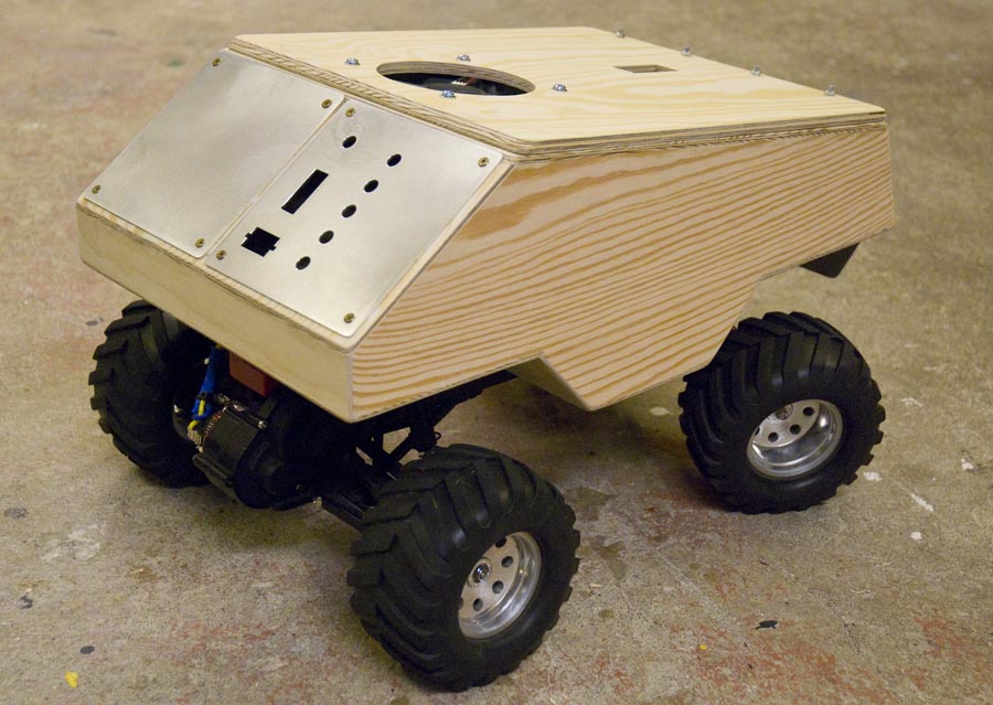
Robot 3 (AGV)
This is my third robot. It is built on an old R/C car. This robot can navigate around a route with pre-programmed way points using GPS. It is powered by a 6 cell 3000mAh NiMh battery pack and it is using the original motor and transmission from the R/C car. The speed control is a standard ESC for R/C cars with proportional forward and reverse drive.
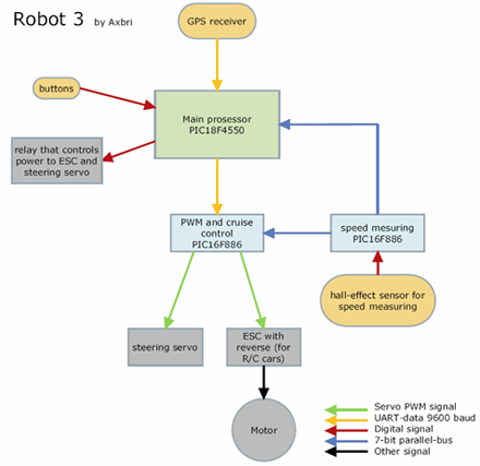
There are three PIC micro controllers in this robot. One of them, a PIC18F4550 is the main processor. It listens to the data from the GPS receiver and calculates heading and distance to the next waypoint. Then it calculates control-values for the ESC and steering servo and sends them through an UART to a PIC16F886.
This processor (called "PWM and cruise control" in the diagram) receives the control-values from the main processor via interrupt. It also receives speed data from a third PIC. To calculate how to adjust the speed to keep it constant, the processor uses a PD-algorithm (proportional derivative algorithm).
The third processor (called "speed measuring" in the diagram) measures the speed of the vehicle. It measures the time between two pulses from a hall-effect sensor mounted in the hub for the left front wheel. There are four magnets glued to the inside of the wheel which makes four pulses in one revolution of the wheel. The processor then calculates a value that is proportional to the speed and sends it on a 7-wire parallel-bus to the two other processors.
The speed data on the 7-wire parallel-bus is not used in the main processor now, but I plan to use it to make the robot steer less when it drives fast and steer more when it drives slowly.
There is also a relay that controls the power to the ESC and the steering servo. The relay is controlled by the main navigation PIC. This makes it possible for the navigation PIC to switch off the power to the ESC and the servo when the robot stands still and waits for GPS to receive satellites, or when the robot has completed the pre-programmed mission.
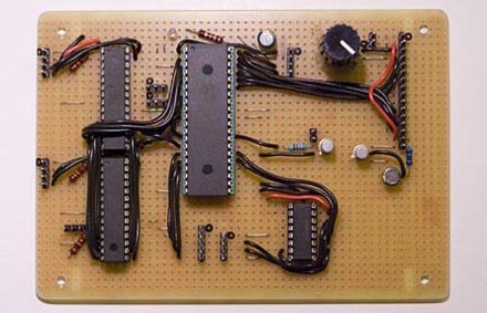
The circuit board containes all three PIC controllers and the RS232 signal converter for communicating with the GPS.
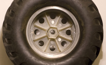
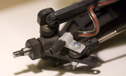
Hall-effect sensor for measuring speed.
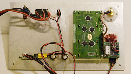
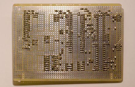
The backside of the front panel. All the wires from the panel have connectors which makes it possible to remove the panel completely from the rest of the robot.
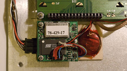
The GPS receiver with backup battery. This GPS uses an external antenna.
Update 25/4 2011
Previously I forgot to mention anything about the LCD. It is connected to the main navigation MCU and I use it as a part of the HMI (Human Machine Interface), and also for debugging.
The robot is updated in three ways: The battery capacity is increased with new battery packs, the motor is swapped to a more suitable one and the firmware is improved.
The power is delivered from two separate battery packs connected in parallel via two shotkey diodes. Each pack now also has 7 cells instead of 6. The original 20-turn motor died, and is now replaced by a much slower 55-turn "crawler type" motor.
The new firmware makes it possible to walk around the route with the robot and save the waypoints directly into the robot memory. This is also shown in my new video. The cruise control is also improved by adjustment of the P-and D-parts in the control loop.
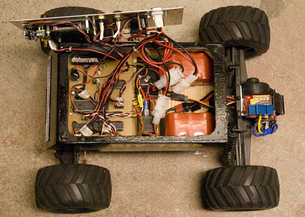
The "electronics box".
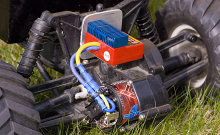
The new 55-turn "crawler type" motor
Update 17/6 2012
I have a couple of ideas on how I wanted to improve this robot. But I have some problems with the GPS receiver, as soon as the robot starts driving it looses its signal. I also want more computer power and more room in the electronics box. So I have decided do build a new robot instead.
I will post this as a new robot when I have something interesting to show.
navigate around a route with pre-programmed way points
- Actuators / output devices: DC motor and R/C servo
- Control method: pre-programmed route
- CPU: PIC18F4550, PIC16F886
- Power source: 2x 2000mAh NiMh battery 8.4V
- Programming language: C
- Sensors / input devices: GPS
- Target environment: outdoor