


RoboDoc
Introduction
A while ago I accompanied my 14 months old daughter to the hospital for a required checkup. Beside some other examinations, the doctor measured her pulse rate at rest with a finger clip photoplethysmograph. The in her eyes strange looking apparatus, the beeping at every heartbeat and probably also the finger clip scared her and she started to cry. Ugh. In this moment I thought: Why - especially for infants and children - medical devices look and behave like medical devices? It would be so much cooler, if the devices would look like funny robots, and the kids have fun during the examination, checking out the robot and maybe forgetting totally, that the robot is just examining them. With this idea in my head we went home and on the next day, I started to design a heartbeat monitor robot for kids.
Design
The robot should consist of an animated head and a cubical main body with the heartbeat sensor, a push button and a loudspeaker for speech output. I always liked the Tengu, a USB-powered device whose LED facial expressions react to sound, making it appear to sing along to music.
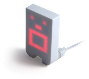
Fig. 1: LED face Tengu, designed by Crispin Jones
To use a LED dot matrix has also the advantage, that simple graphics like a heart, animations like lip movements and text and numbers can be displayed. As I still had a stylish blue 5 x 7 square LED-dot-matrix display lying around, I started to design the head around this display. I put two robot eyes as described here above the LED-dot-matrix display and packed it in a white ABS box. The final design, using Sketchup, can be seen in fig. 2. For simplicity the LED-dot-matrix display is directly driven by the output pins of a Picaxe 28X2, which is placed in the head. The LED eyes and the LED-dot-matrix display are controlled by a RX (serin) and TX (serout) line. The schematic of the head can be found in the attachments.
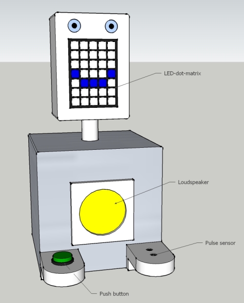
Fig. 2: Final design
I wanted the head to be turnable by 1 DOF to show the result of the measurement and facial expressions into different directions (e.g. patient and doctor). As it has to be assumed that the kids will play with the robot, the pan unit needed to be very rigid, so I reinforced the connection head-servo shaft by a load bearing servo block from ServoCity.
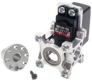
Fig. 3: Load bearing servo block for standard HITEC servos
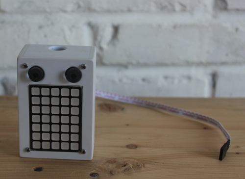
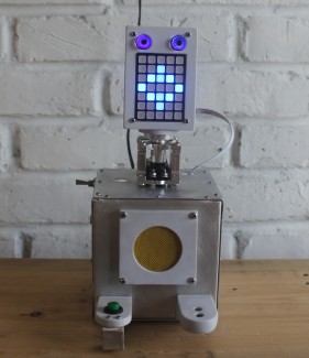
Fig.4: Finished robot head with enclosure, made from 2mm ABS sheet
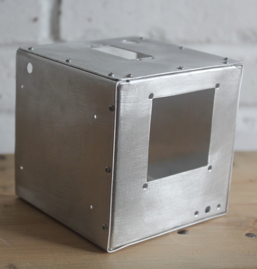
Fig.5: Main body with all the cut-outs and bores, made from 1mm aluminium sheet
The most critical part on the robot was the heartbeat monitor sensor. In general there can be two modes used for a photo-plethysmography (PPG) sensor, as shown in following figure: reflection (for example finger) or transmission (for example earlobe). Normally a LED with a wavelength in the nearinfrared is used because with this wavelength the strongest modulation of the signal can be achieved due to light absorption in the haemoglobin of the blood. The principle of the two sensor is the same. The heart rate is measured by sensing the change in blood volume in the finger or earlobe. The reflected/transmitted signal is detected by a photo diode or photo transistor. The changing blood volume with heartbeat results in a train of pulses at the output of the photo sensor. The magnitude of the signal is too small to be detected directly by microcontrollers. Therefore according operational amplifiers (OpAmps) have to be used to filter and amplify the signal to a certain voltage level so that the pulses can be counted by a microcontroller.
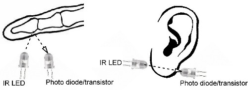
Fig. 6: The two types of PPG sensors. IR light is transmitted into the finger pad, reflected by the bone and detected by a photo diode/transistor. IR light is transmitted through the earlobe and detected by a photo diode/transistor
Both PPG sensors have advantages and drawbacks. The transmission type usually requires a clamping device, where the IR LED and the photo transistor are mounted. The reflection type can be implemented in a surface, but is also sensitive to movements of the finger during measurement. As kids feel not comfortable with a clamp on their extremities (I guess most adults as well), I decided to use the reflection type.
The heartbeat sensor schematic (fig. 7) I am using is from Embedded Lab, an online teaching laboratory for Microcontrollers and Embedded Systems. The IR-LED is a IR333C, the photo transistor a PT334-6B.
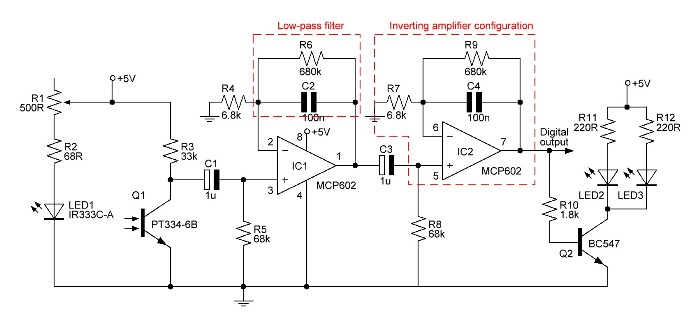
Fig. 7: Heartbeat sensor schematic with indicated low-pass filter and inverting amplifier configuration
The gain of the inverting amplifier configuration of each stage is calculated by
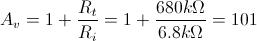
The total gain is the product of the gains of every stage, therefore 10201.
The cutoff frequency of the active low-pass filters is given by

This means the maximum measurable heart rate is approx. 140bpm, so if higher pulse rates need to be measured, the filters have to be changed accordingly. As the robot shall be mainly used for children between 1 and 10 years (normal pulse rate at rest 70-130 bpm), II'll keep this low-pass filter configuration for the moment.
C1/R5 and C3/R8 are actually passive, analog, first-order high-pass filters. They are used in the circuit to block the DC component in the signal.
It turned out that the servo produces electrical noise even its signal pin is set LOW, which disturbs the sensitive heartbeat monitor circuit. I solved this problem by using a N-channel MOSFET to enable/disable the power supply for the servo completely during measurement. This has also the nice side effect, that the servo jitters not anymore uncontrolled around during switching on the robot.
Next figure shows the heartbeat monitor circuit built on a perf board. The sensor housing is made from 1 and 2mm ABS sheets, glued together by the sandwich method with super glue. There are two blue LEDs hidden under the first layer of ABS sheet. As soon as the finger is placed on the sensor, the blue LED's starting to light up with the heartbeat.
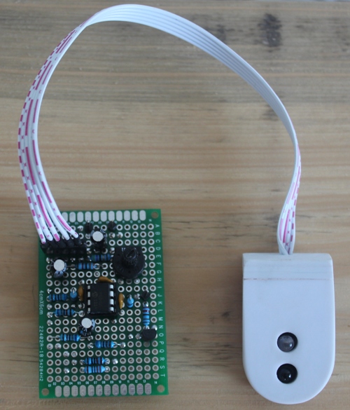
Fig. 8: Heartbeat monitor circuit and sensor
Next, I wanted to add speech to guide the patient through the measurement process and give a brief diagnosis at the end of the measurement . As I messed totally up with my SOMO 14-D MP3-player module, I went back to the ISD2560 voice recorder IC. The ISD2560 is a single-chip voice record/playback device with a duration of 60 seconds. It is easy to control by a microcontroller. The ISD2560 has 10 inputs (A0-A9). These 10 inputs representing a 10 digit binary number according to which logical level is applied to every of these inputs. If you convert the binary number in a decimal number and devide this decimal number then by 10, you have a value in seconds, where the playback/recording starts. You can imagine an audio tape with a total duration of 60 seconds and a reading head . If you apply for example the binary number 0010010110 to the output pins, the reading head moves to the position 15 seconds ([0010010110]2=[150]10. 150/10s-1=15s) towards the beginning of the audio tape, which is equal to 0 seconds. At this position you can playback then an already recorded voice or record a voice with a max. rest duration of 45 seconds.
In the moment I have recorded following speech:
- Put one of your fingers on the sensor. Observe your pulse via the blue LED's. If you are ready, press the button for 3 seconds. The measurement takes 10 seconds (approx. 12 s)
- You can remove your finger now (approx. 3 s)
- If you are a child 1 to 10 years old (approx. 3 s)
- If you' are a child over 10 years old or an adult or a senior (approx. 5 s)
- Your pulse rate at rest is normal (approx. 3 s)
- Your pulse rate at rest is too high (approx. 3 s)
- Your pulse rate at rest is too low (approx. 3 s)
The table in fig. 9 shows the according settings of the A0-A9 inputs. A0 and A9 can be tied to ground, as their are always logical low.
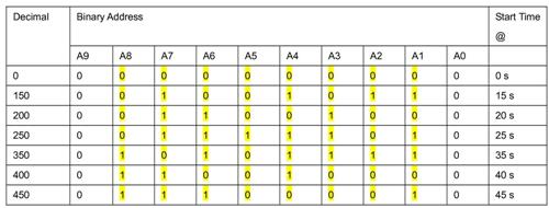
Fig. 9: Logic table of ISD2560
The microcontroller playback mode is as following:
- Address pins in according configuration
- PD pin LOW
- P/R pin HIGH
- CE pin pulsed LOW (HIGH-LOW-HIGH)
- EOM pin will pulse low to indicate end of message
The schematics of the speech module and audio amplifier (LM368) can be found in the attachments.
As the quality of speech would be significantly decreased at any record, I needed the highest possible quality of TTS (Text To Speech) input. There are many free online TTS tools, but very less have high quality speech, free choice of speakers, speed, pitch, etc. I finally found Readtheword.com, which gave satisfying results. Unfortunately only 8 readings are for free, but you can register new, and have another 8 readings for free.
During the tests I noticed that the volume and quality of speech output can be improved a lot using an according soundbox for the loudspeaker. I experimented with different cardboard boxes to find the right volume for the used 8Ω/0.5W speaker. After I found the optimal ratio, I built the soundbox by ABS sheet.
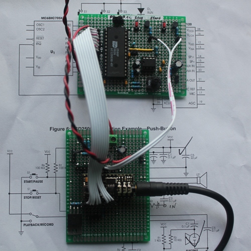
Fig. 10: Main and speech board
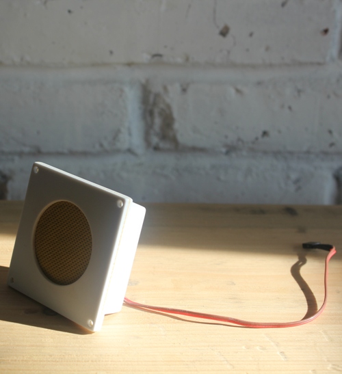
Fig. 11: Home made ABS soundbox for the loudspeaker
For convenience I wanted to use a wall transformer to power the robot. As most wall transformers have insufficient stable DC outputs (they mostly only use on diode to rectify), I added a bridge rectifier on the power input. This has two more advantages. The rectifier acts as a polarity protection (if DC input, polarity doesn't matter) and the robot can be powered by DC or AC.
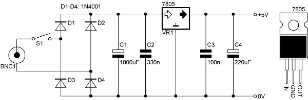
Fig. 12: Schematic of power supply
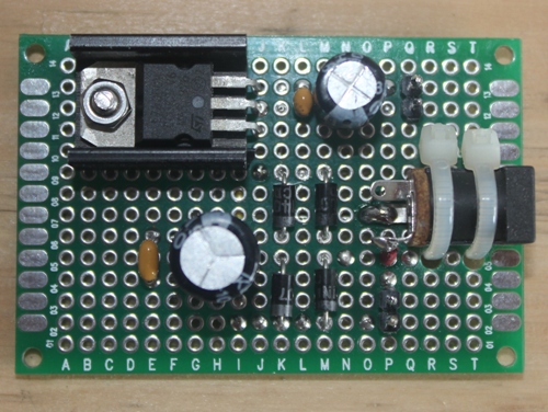
Fig. 13: Power supply circuit built on a small double sided perf board
After I had built all parts and electronics, tested them and programmed the microcontrollers, I finally assembled the robot. The following pictures showing the assembling process step by step.
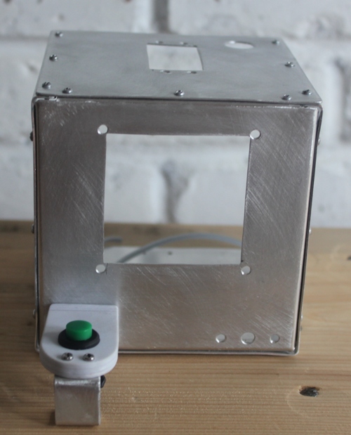
Fig. 14: Foot with press button attached
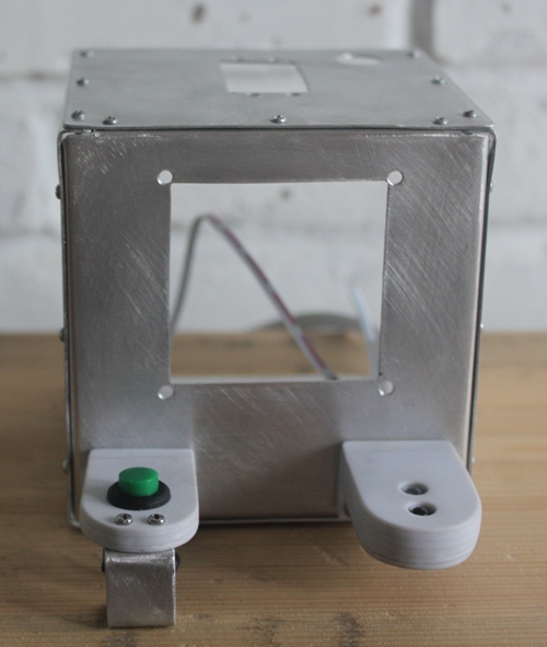
Fig. 15: Foot with heartbeat sensor mounted
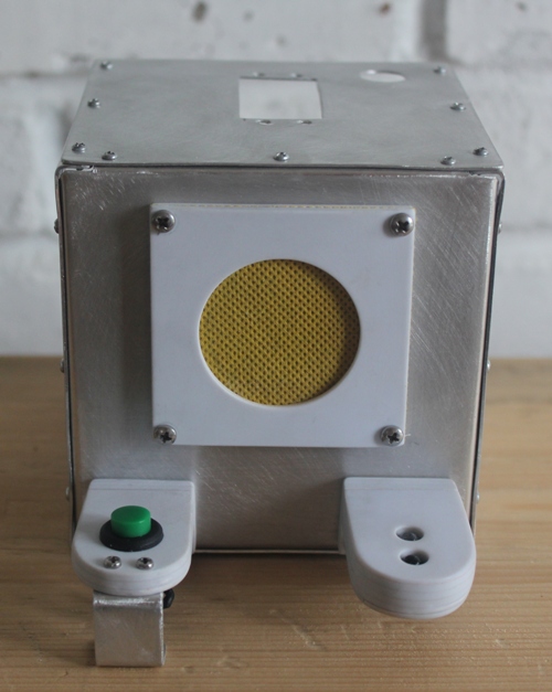
Fig. 16: Loudspeaker box fitted
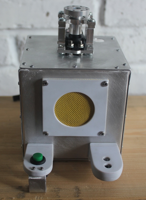
Fig. 17: Head pan unit on its place
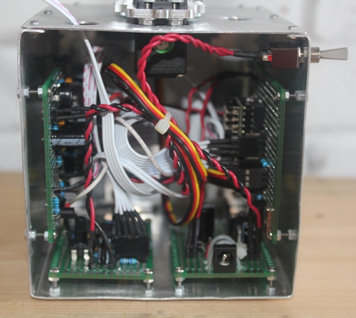
Fig. 18: Complete electronics inserted
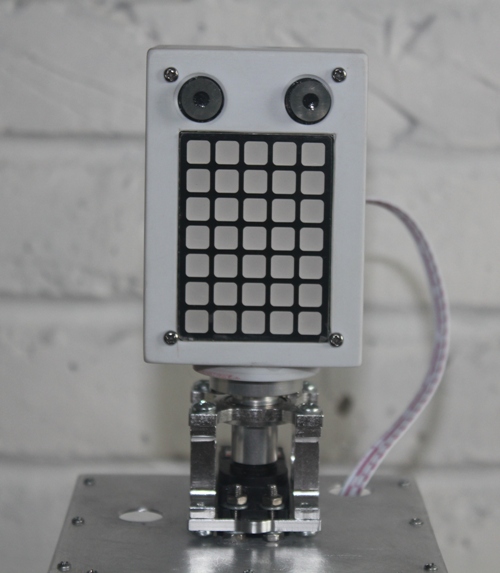
Fig. 19: Head assembled
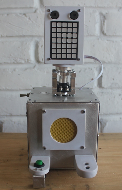
Fig. 20: Completed robot
Further developements
To create a more sophisticated diagnosis system, more sensor data are needed. For example not only the heartbeats per minute, but also the time intervals between two heartbeats could be measured. Other possibilities are for example an optical oximeter for assessment of blood oxygen saturation, skin conductance or body temperture. I have tried to measure the body temperature on the finger with a DS 18B20 temperature sensor, but failed. The temperature rises up quickly to around 3 or 4 °C above the room temperature, but it takes then endless time to get nearby the real body temperature. I guess fingers are not suitable to measure the body temperature reliable - or at least corrective factors have to be used. Another approach would be to measure the temperature of the eyeball by a pyrometer or a thermographic camera. I definitely want to do more research in this interesting field.
****Update 26/08/2012****
Just finished an earlobe heartbeat sensor for RoboDoc v.2 as an addition to the touch heartbeat sensor. The new heartbeat circuit will have a digital and analogue output as well for oscilloscope display and analysis. As I want to do a so called Poincaré plot and therefore need to solve integrals, I probably will use the Max32 with the MPLAB® IDE.
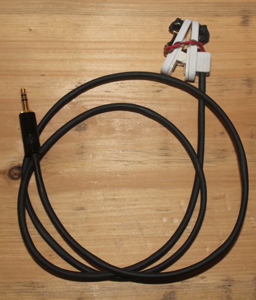
Fig. 21: Homemade earlobe heartbeat sensor
I also found an interesting sensor to measure body temperature.
RoboDoc will be shipped tomorrow to Andrew for the Maker Faire to check peoples heartbeat.
Measures the pulse rate at rest and gives a brief diagnosis
- Actuators / output devices: loudspeaker, 5 x 7 LED dot matrix, servo to turn the head, 2 LED robot eyes
- Control method: autonomous
- CPU: 2 x Picaxe 28X2
- Operating system: Windows 7
- Power source: 9 V wall transformer
- Programming language: Picaxe basic
- Sensors / input devices: Photoplethysmograph, Push button
- Target environment: indoors, examination rooms or at home