


Robocup Robot
This is my robot that I am going to use for the Robocup Junior Australia competiton. We have to make a journal anyway so I figured that I might as well upload it here.
Sorry about the quality of the videos, they used to be 1080p but I am running low on internet. (I only have 15GB per month)
Testing the electronics before the case is designed. After a bit of tweaking and internet research, getting the sensors to return some readings was quite easy.
In the picture is the board, 2 servos, 2 motors, battery packs, the sensor array, distance sensor and a touch sensor (switch).
The original plan was to use the metal geared motors on the left but they were too big so I found smaller motors from another electronics set I had. At $37 a piece my mum wasn't impressed that they were not used in the robot.
You can see that the original red design is much bigger than the blue design, it only left a few centimetres of clearance on each side of the width restrictions. The blue design is being used at the competition today only that particular one snapped so I had to re-print it in white.
This is the design for my robot being printed. The two rectangles furthest from the camera are used to mount the motors. The back rectangle is the jockey wheel/slider.
This is the robot base finished and assembled. It has the motors and all of the sensors apart from the one touch sensor.
After a week away on holiday, I made a start on the arm mechanism. I had the idea of making the mechanisms for the robot out of LEGO. This was mostly because it can be easily tweaked if I see any problems and it makes for smoother moving parts than 3D printed plastic.
This was my first try at making a LEGO compatible printed part. I was surprised by how well the parts lined up with the holes in the beams. The only problems were the imperfections that you can see on the side of the part in the picture (as a result of my printing) and the fact that the centre of the beam did not line up with the centre of the rotation axis of the servo (which you may not be able to see). So I tweaked the design of the part and printed again.
You can see that the before mentioned problems have been fixed with this new part.
After making a part that converted the servo horn to LEGO, the beginnings of a robotic arm emerged. This process went seamlessly and there were no problems. Next was to print out a part for the servo to fit on the end of the arm.
Here are those parts printing.
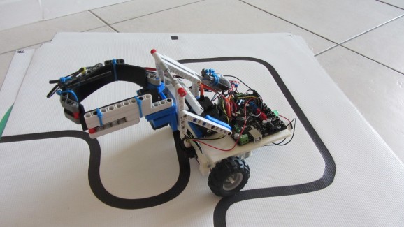
This is what it looked like after some assembly.
Testing it picking up the can. (not programmed)
The arm is designed in such a way that the can will always be level, no matter what height the arm is at. This design also uses 2 servos, this is not possible with an NXT and was the main reason that I built a custom robot. It also has enough pins for many, many more sensors than the NXT.

After programming a simple line follower, using two light sensors, I came across a design flaw: to get enough torque to move, the speed of the motors had to be increased too much (the gear ratio was too high). To try and fix this problem I used the smaller LEGO wheels (with the help of a 3D printed converter). Using these wheels effectively reduced the gear ratio and therefore allowed for more torque, but at a lower speed.
Thanks to Chickenparmi, Maxhirez, Kariloy, Birdmun and Chris the Carpenter for helping in the shout box.
Special thanks to Chris for his answering my forum post with regards to the sensors.
Follow line and rescue a victim (soda can)
- Actuators / output devices: 2 servos, 2 geared motors
- Control method: fully autonomous
- CPU: Arduino Atmega 328 (DFrobot Romeo Controller)
- Operating system: Arduino
- Power source: 7.2 lipo
- Programming language: Arduino C++
- Sensors / input devices: Sharp IR, switch, IR line sensor, homebrew light sensor
- Target environment: Controlled Competition Environment