


Revenge of the Hexapod, the Quadruped that never worked.
3 years pass since I progressed; now I know a little program the PIC
My goal in this new project was to create a robot worthy of the name, programmable! With a microcontroller I managed to find a 16f84!
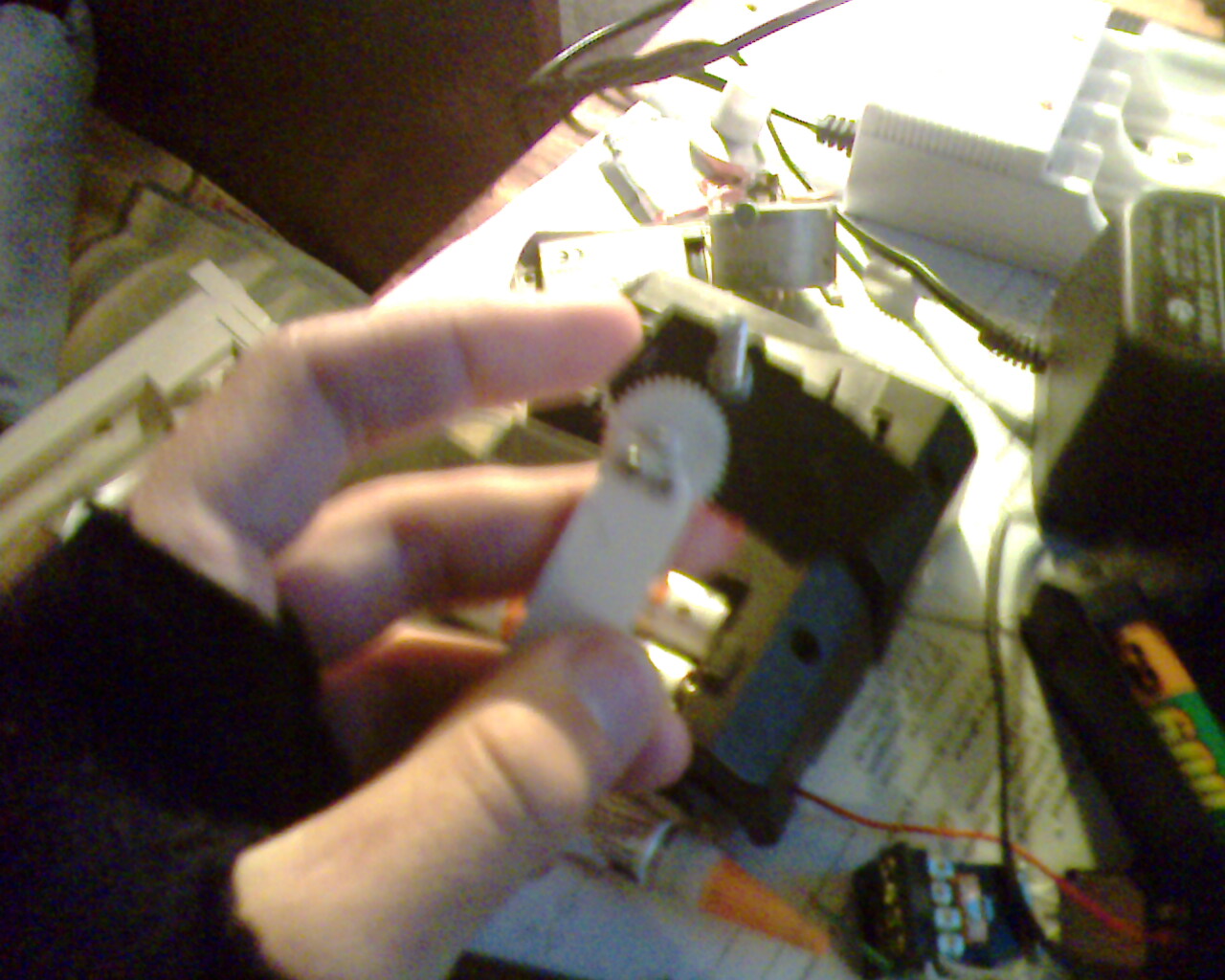
I haven't Servomotor so this is what I did! I bought 8 toys "made in china":.....Brutally sacrificed!!!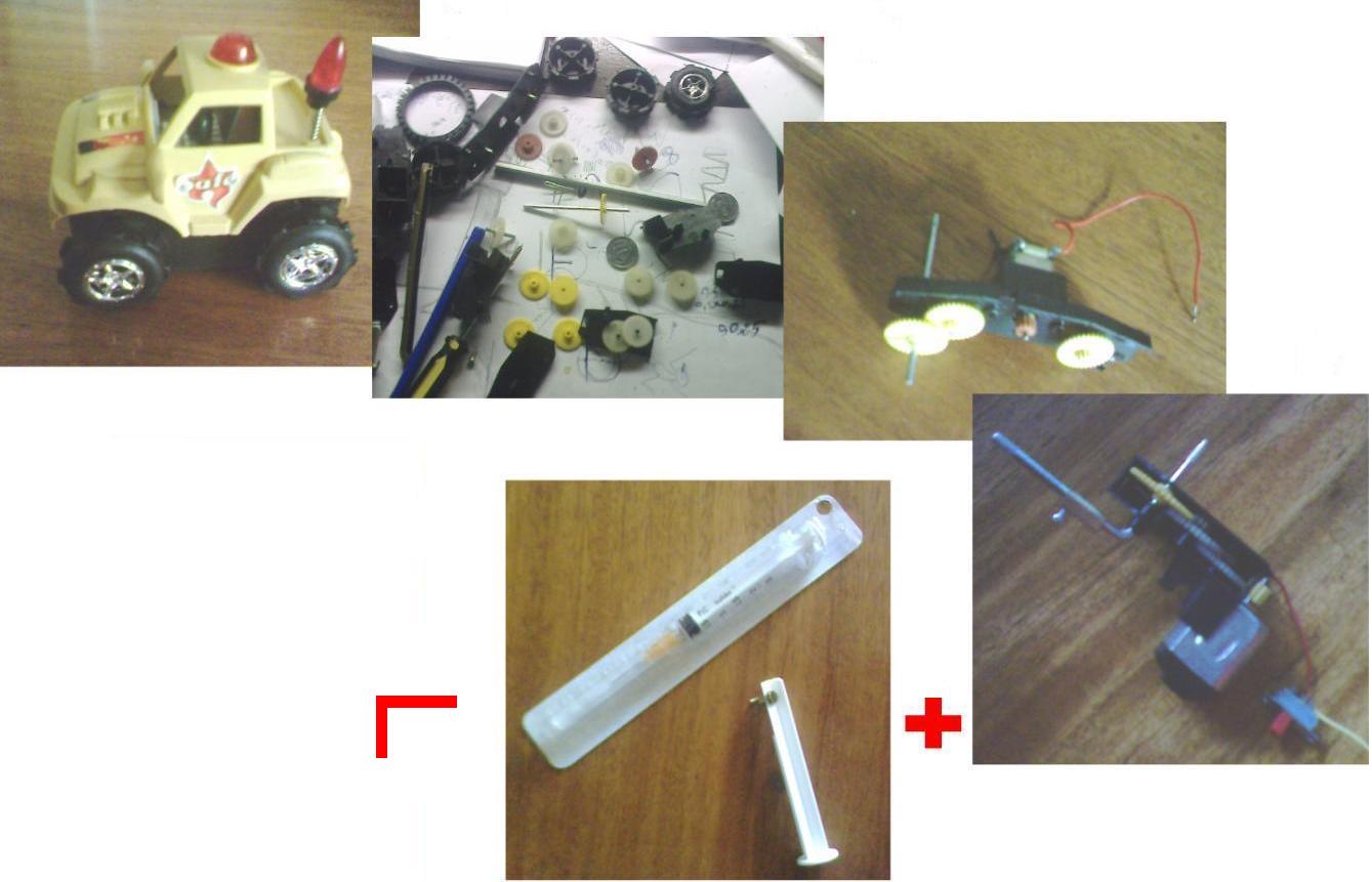
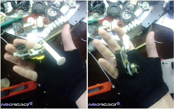
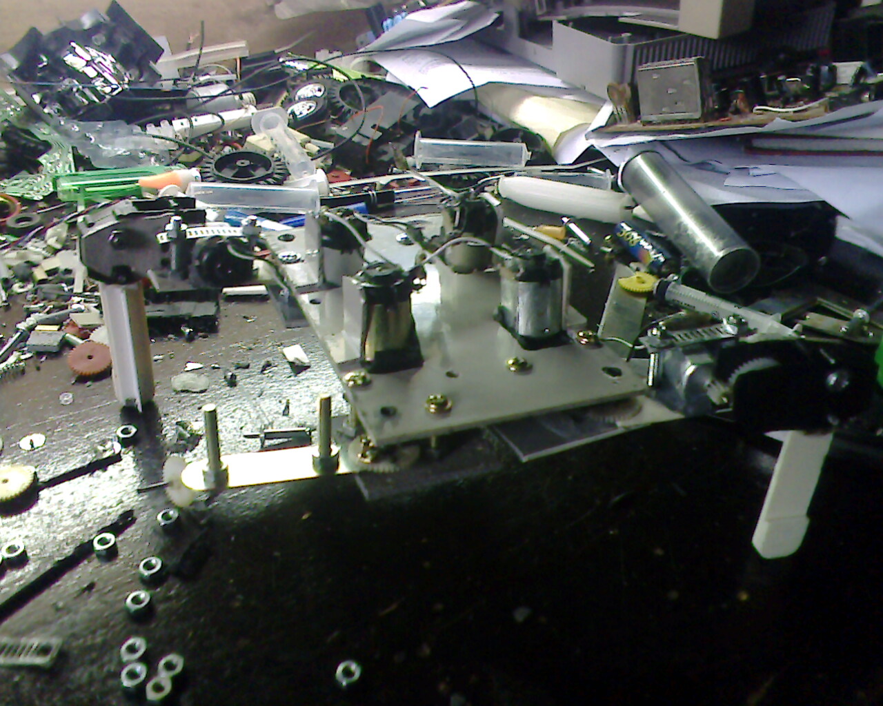
The mechanical part of the servo was successful.
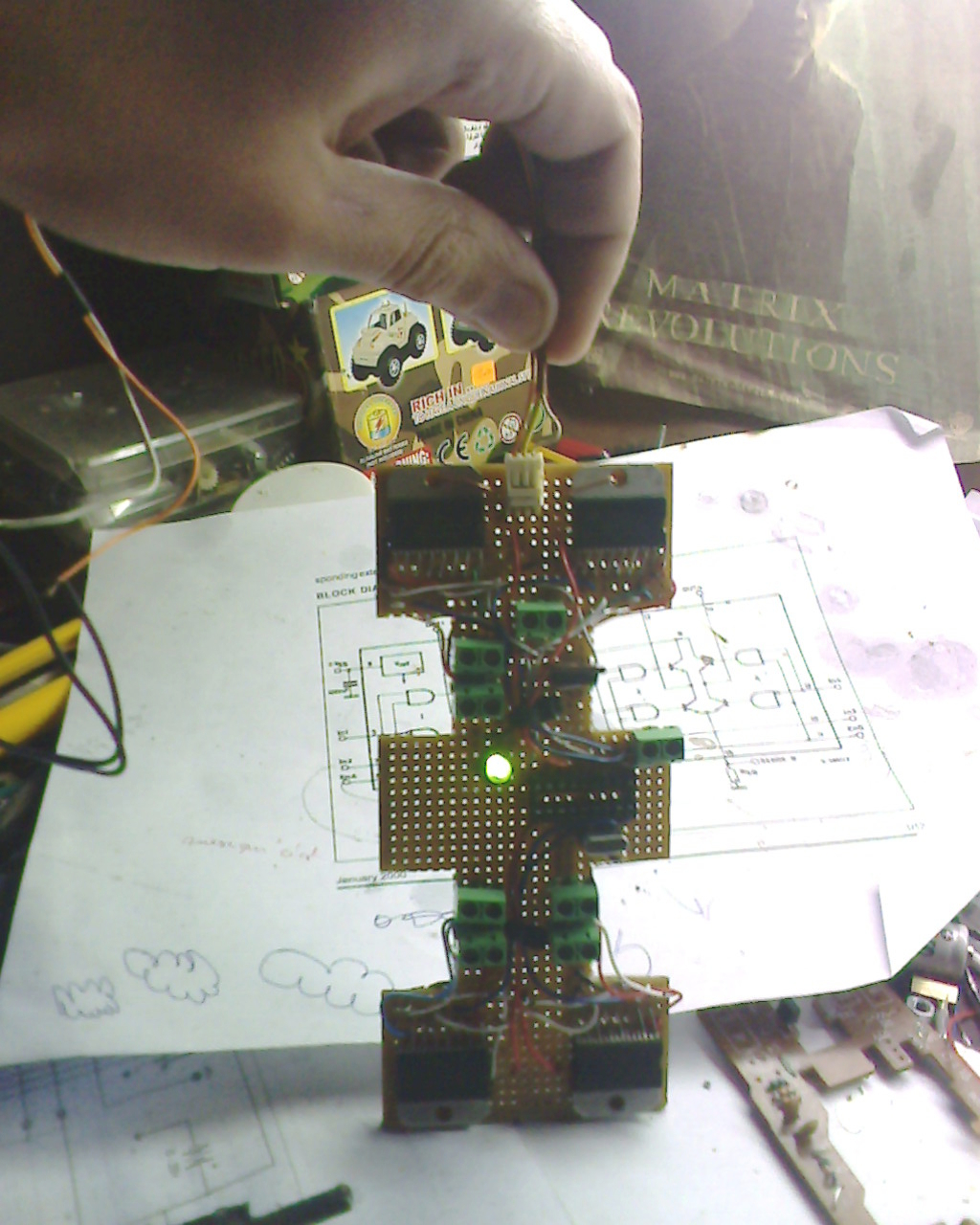
For the electronics part I took a L298, I find it difficult!!, because I could not use a classic H-bridge, coz I had 8 motors, so 8x4transistor = 32! Transistors!
The board to control the 8 motors:
For the chassis, I took a "nintendo" lol (I hope that there is not collectors).
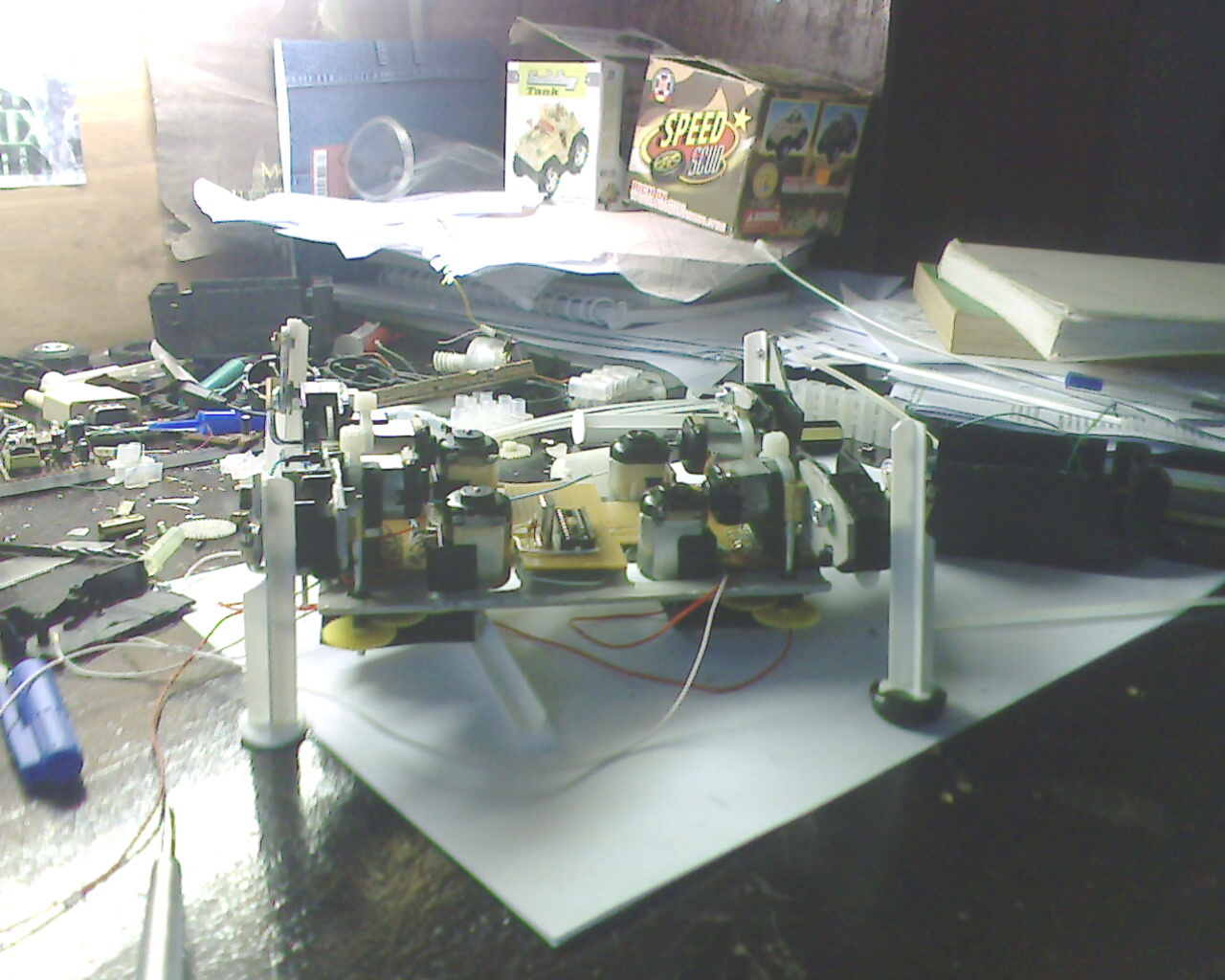
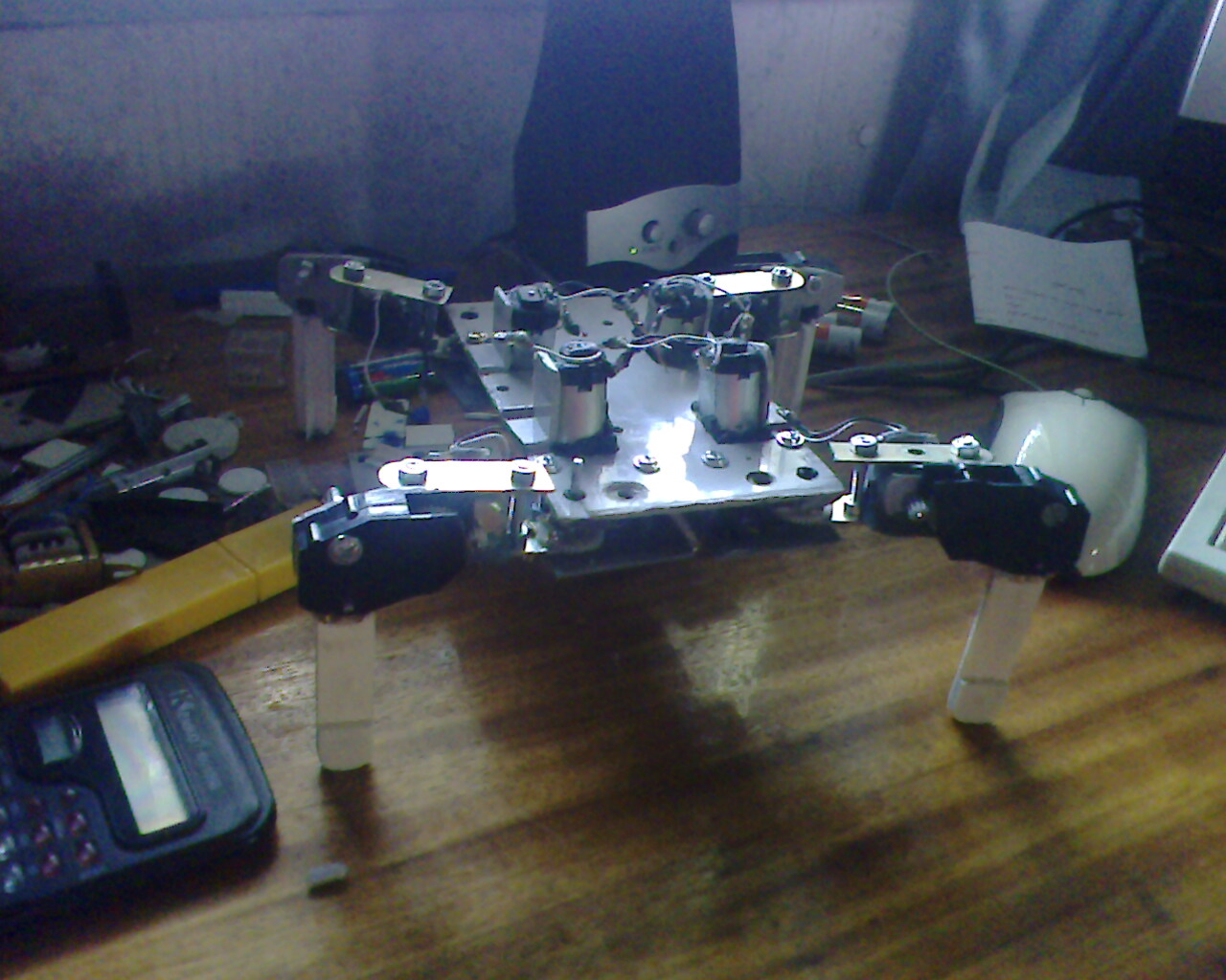
All this has given this:
the robot on its 4 legs!
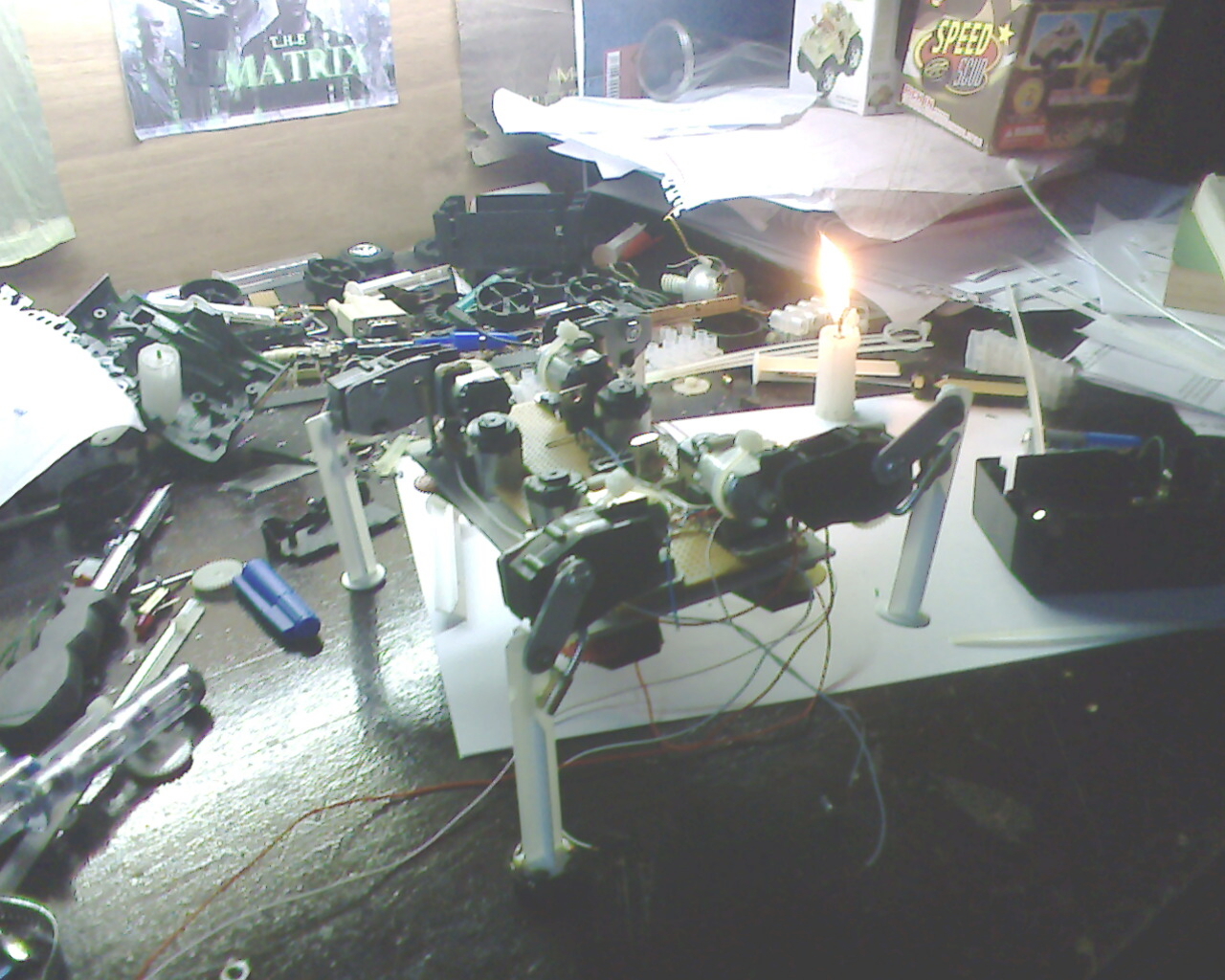
After lots of trials I changed the form of the robot.
Cause of all its changes is that! : 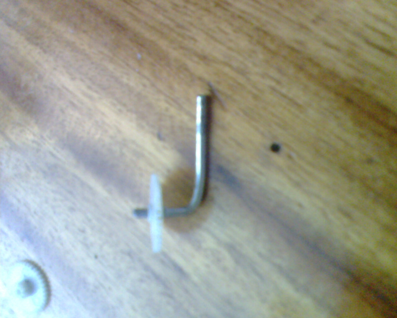
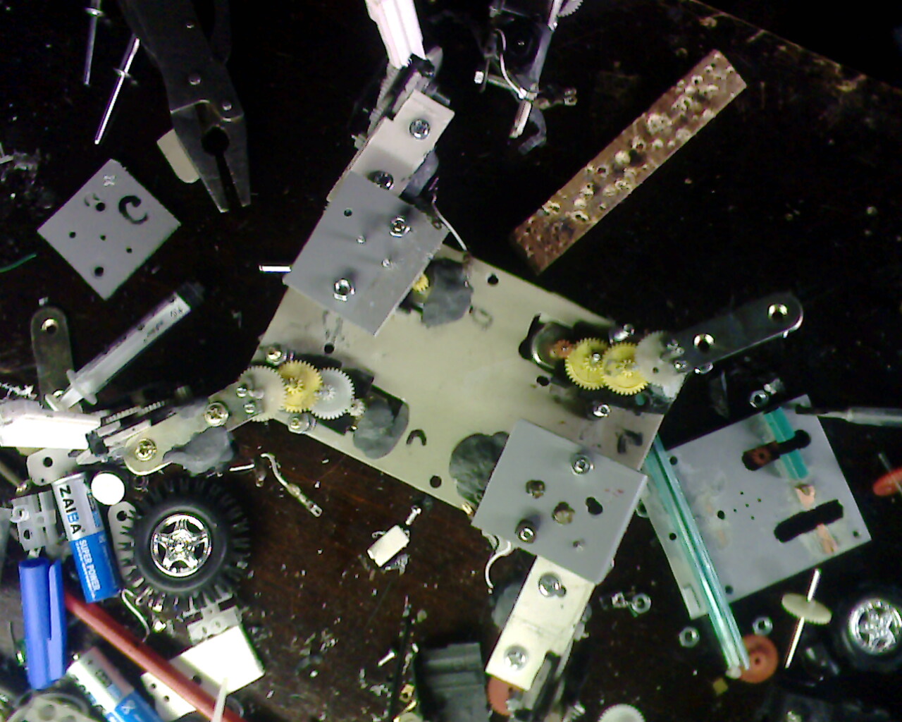
Over time axis in the gear walls become less resistant
So the solution is to set the leg directly on the gear walls with small bolts!
so :

after that I still change for the same cause:
Well as you know the pic 16f84 hase only 12 port, so for i can control my 8 motors I need 8x2 (L298 ports) = 16 ports! ....
The solution:
- Connect the 8 outputs (in2) of 8 H-bridge with a single port of PIC. (We call it "common port”).
- Connect the other 8 out (in1) remaining with 8 port PIC.
Which mean I will use 9 ports only.
And this is what it gives:
- If I went to turn the motor (which is connected with the port1 for example), "port c" must be on 0 and port1 on 1, and all other ports should also be on 0 (in these way it well be brake).
- And if I went to turn the motors in the other direction, the "port c" must be on 1 and port1 on 0, and all other ports should be on 1 too!.
But the programming will be a slaughter lol but it is the only solution!
Example:
"start
;commune état 0
;A
movlw 0xFA
movwf PORTB
movlw 0xA
movwf PORTA
call tempo
call tempo
movlw 0x10
movwf PORTB
movlw 0x1
movwf PORTA
call tempo
call tempo
movlw 0xEF
movwf PORTB
movlw 0xF
movwf PORTA
call tempo
call tempo
;c
movlw 0x2
movwf PORTB
movlw 0x4
movwf PORTA
call tempo
call tempo
movlw 0xFD
movwf PORTB
movlw 0xF
movwf PORTA
call tempo................."
But with these solution my motors will not run in two different directions simultaneously, but it did not bother the walking of the robot.
All these because…..16f876 is expensive for me X) , and I think it's too much for this project! :)
finally it was a failure .... hei! but it walked some minute!
But I could not film it :(
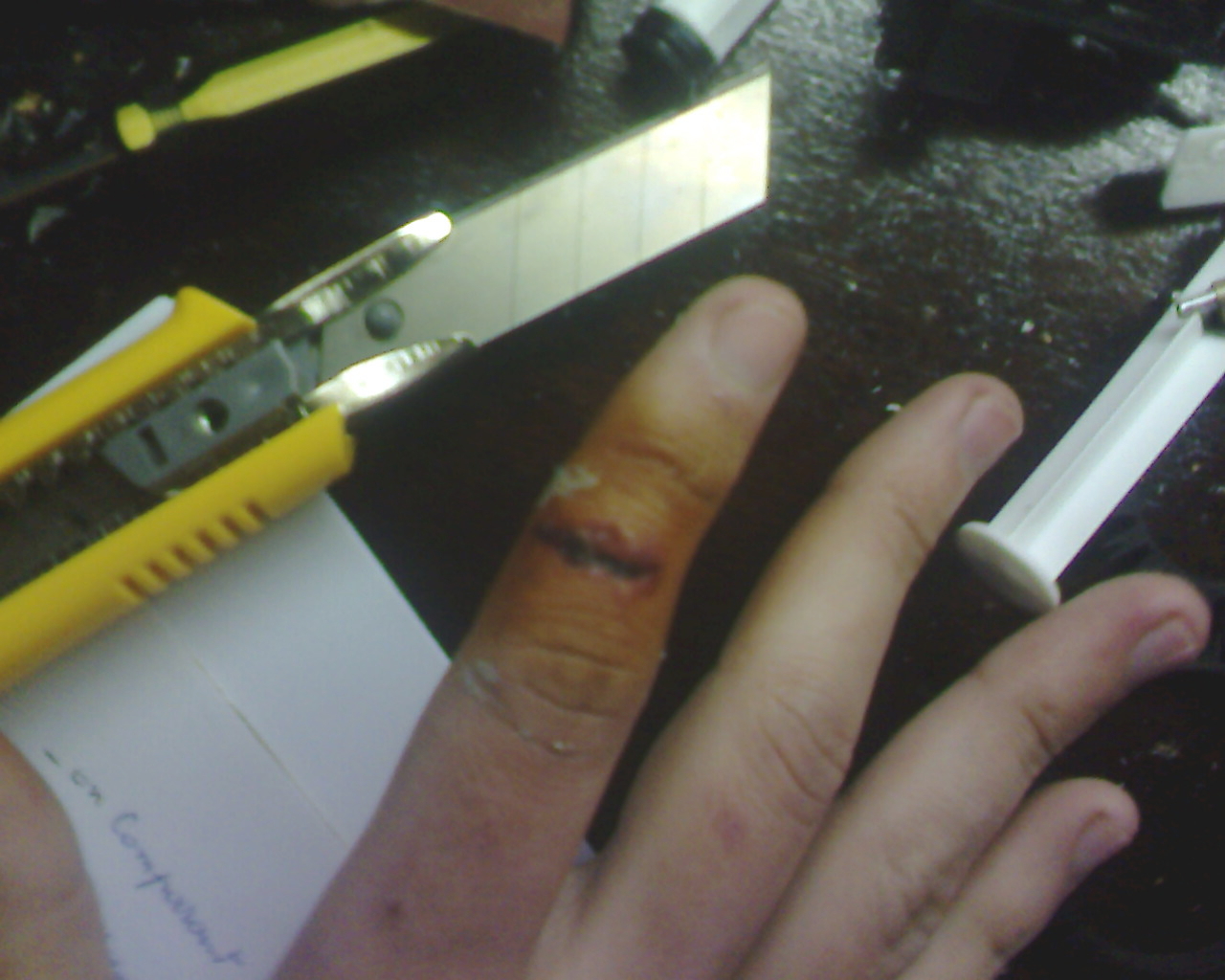
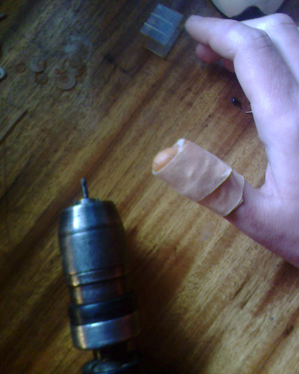
heu…hei the war wound interests you?
- CPU: PIC16F84
- Power source: 12v
- Programming language: Assembler
- Target environment: any where