


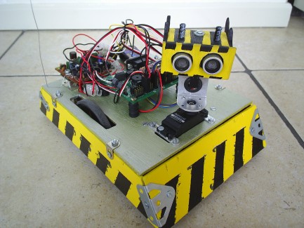
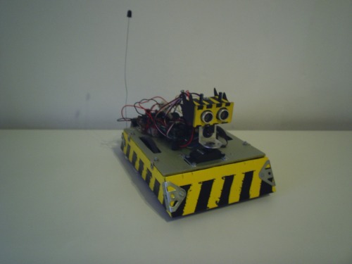
Rebel II
This is the second robot that I've ever build. The first robot was Rebel. But this robot had some limitations and shortcomings. The things it missed are among other things, a real third wheel (now it was just a plastic cap that dragged over the floor), on/off buttons (every time I want to put it on I have to connect the batteries, remote controlling (I'd really like to know if I can make it remote control with a PCB from an old RC car I had lying around). First I started to design my new robot in a CAD program. I then cutted the pieces I needed from wood. Everything is designed the way that I don't need any glue, so this robot can be fully dissasembled and assembled again with screws. I went to the store I bought me some toggle switches, one for turning the Bot board II on and one for turning the servo power on. I also bought a office-chair-wheel to use as a third wheel, to keep to robot balanced. For all the other parts I took apart Rebel.
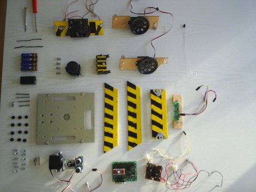
The parts I used for Rebel II are:
- 2x Continuous rotation servo
- 1x Standard servo
- Basic Atom Pro 28
- Mini Atom Bot Board II
- Ping))) Ultrasonic sound sensor
- Tracker sensor v3
- 2x Wheels
- office-chair-wheel
- Old RC car PCB
- 4 AA battery holder
- 9V battery clip
- 2x toggle switch
- wood
- paint
- screws
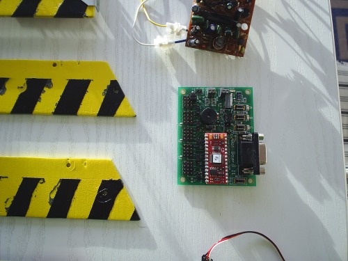
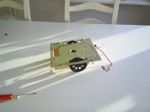
On the picture below the Mini bot board II (green) is shown with the Basic Atom Pro 28 (red) mounted on it. Also a part of the RC car PCB is shown (brown).
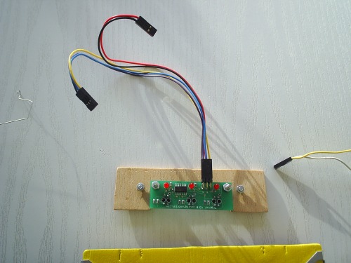
The picture below shows the tracker sensor v3. This is a prefab line following PCB. It has three infrared sensors mounted on it. This PCB is connected to the Mini bot board II by 2 cables. One cable gives the tracker sensor current (the red/black cable), the other cable are 3 inputs. One for each infrared sensor. The inputs become high if the infrared sensor "sees" white, and become low otherwise. Nice thing about this board are the three leds mounted on top of it. These are on if the infrared sensor below them sensors white, and are off otherwise. This way you can see really fast if your PCB is working or not, you don't even have to hook the input cable to a microcontroller. Just connecting the power cable is enough to test the infrared sensors.
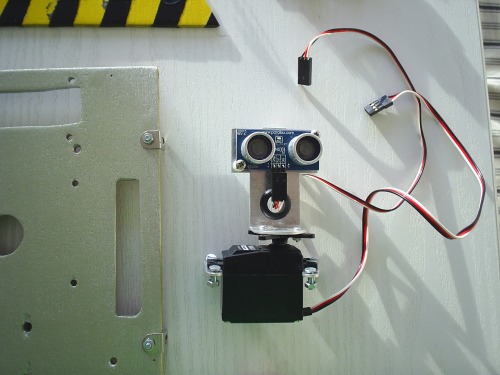
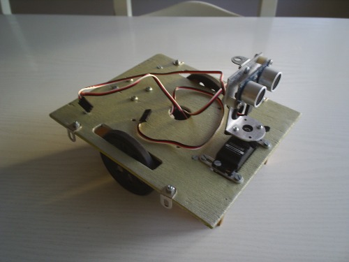
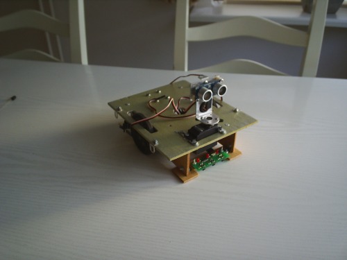
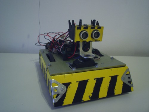
The picture below shows the ping))) Ultrasonic sound sensor mounted on a standard servo. This ping has 1 cable which is very easy mounted onto the mini atom bot board II. The ping uses 3 wires, 1 GND, 1 PWR and 1 for triggering and measuring. In order to use this sensor your microcontroller must be able to switch an input port to an output port and vice versa, most microcontrollers are capable of doing this. The servo is also very easily mounted onto the mini bot board by a connector cable, which also uses 3 wires. 1 for GND, 1 for PWR and 1 for signal. The servo can be controlled by sending pulses to it. Depending on the pulswidth the servo turns left or right. Sample code to make the servo turn for the Basic Atom Pro 28 is:
servopin CON P0
Main:
Pulsout servopin, 4800
Pause 20
Goto Main
Similar code makes the continues rotation servos rotate. And thus makes my robot move :)
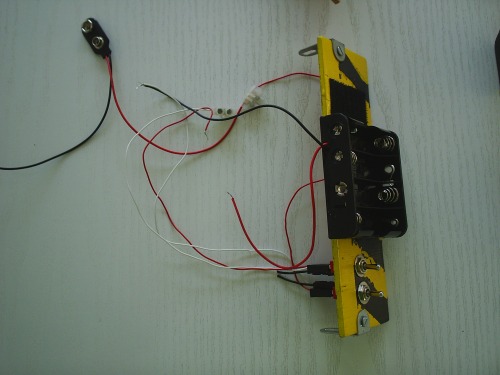
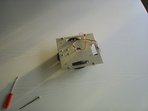
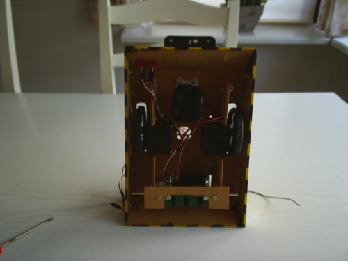
In the picture below the two toggle switches are mounted onto the back plate of the robot. Also the 4AA battery holder is mounted onto the back plate with screws. The 9V battery for feeding the bot board is mounted with some velcro (shown on the right side of the battery holder). This way the batteries can be easily replaced. One toggle switch is connected to the 9V battery clip and the other toggle switch is connected to the 4AA battery holder. This way they can both be turned on or of.
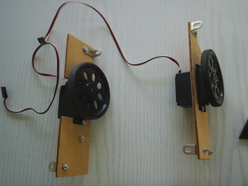
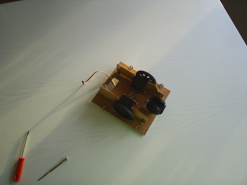
Below are the continuous rotation servos shown mounted on some wooden plates. The wheels came with the servos and fitted on them perfectly.
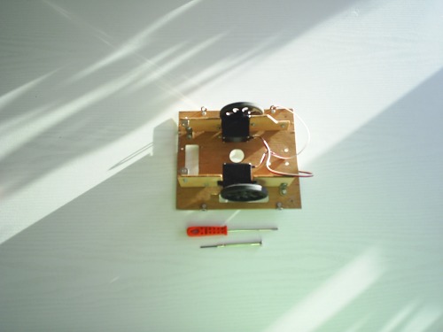
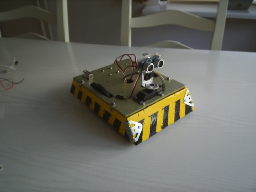
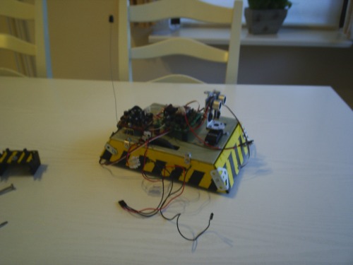
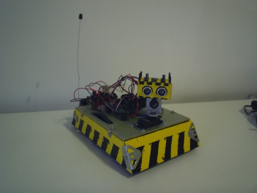
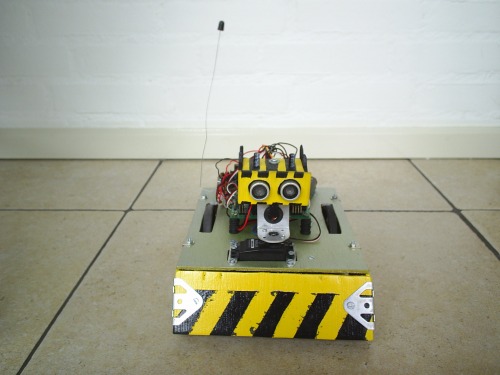
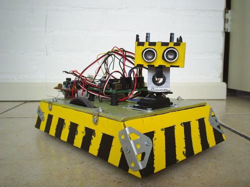
Below are pictures of the proces of assembling the robot. First the wheels are mounted on the base plate. Then the office-chair-wheel is mounted to balance the robot.Then the ultrasonic sound sensor along with the standard servo is mounted on the base plate. Then the tracker sensor is added to the robot and the side plates are screwed to the base plate. After that, both PCBs (bot board II and RC car PCB) are mounted on top of the base plate. And finally the 'head' is mounted on the ping ultrasound sensor.
Because I hope you will learn something from this I included the souce code I used for this robot. It is now capable of obstacle avoidance, line following and remote control. I also have some other programs for sumo and weird line following (turning head while following a line). If you are intrested in these code please ask and I will include it. If there are questions regarding the source code, you are free to ask and I will answer them. Because I'm so in love with this robot I also included a wallpaper. I hope you like this robot as much as I do!
Happy building!
- GobliZ
Navigate around via ultrasound / Remote controlled / Line follower / Sumo bot
- Actuators / output devices: 2x Continous Rotation servo's for wheels, 1x 180 degree servo for controlling the ping
- Control method: autonomous, and/or R/C
- CPU: Basic ATOM Pro 28
- Power source: 4x AA (1.2V) for powering the servo's, and R/C receiver board, 1x 9V block for powering the Bot Board II
- Programming language: Atom Basic
- Sensors / input devices: Ping))) Ultra Sound, R/C receiver
- Target environment: indoor