


Ratbert
05-Mar-09
I've been busy.
- The SpeakJet board is made, and to my amazement works fine. It may not be pretty, but it is better than I expected, and was easier to solder up than I expected. The benefits of planning.
- I've mod'ed my 28X project boart to replace some of the female headers I added earlier with header pins - must improve my desoldering! Then spent an evening making female to female fly leads to connect the various Ratbert components. these turned out to be easier and quicker to make than I expected despite using snipes rather than a crimp tool (too expensive at c. GBP 200!)
- The Servo and SRF05 have each been connected up and proven with short test programms gathered from elsewhere on LMR (thanks Frits). The servo gave me a few problems. For a couple of hours it would only turn slight clockwise when powered up, then nothing. Eventually I realised that I had the Darlington chip on the project board, and it needs the resistor pack. (I'm using the motor driver chip for the wheels and a third port for the servo). The range of my servo appears to be non-standard 50-200, but 30 minutes of calibration fixed that. At one point I thought I'd blown the SRF05. I expected the red flashing LED to appear as soon as I powered it up. It didn't, and I had the power the wrong way round at one point. As soon as I got the demo program running everything was OK.
21-Feb-09
 Headline news is that Ratbert now moves. I got the PicAxe hooked up to the motors and wrote a little test script to do a sentry beat - forward spin, forward, spin, etc. I should have used GM9 motors rather than GM3s as he moves awful slow. A second, high voltage, power supply may help a bit.
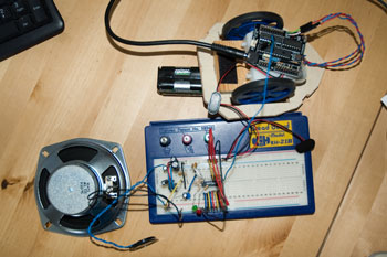
Made a couple of mods to the SpeakJet circuit. The diagram below shows the latest version. Now I need to get this off the breadboard and onto stripboard so that I can get it into Ratbert's body. I'll only use the 2cm mylar speaker, not the 12cm cone that I have hooked up for testing! I've attached a WAV file of Ratbert speaking. Unfortunately, the capture software's not great, so it sounds better in real-life than it does here. I'm sure you'll get his message though.
14-Feb-09
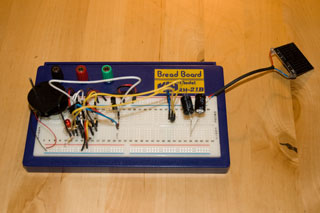
Inspired by Calculon and with help from OddBot I have fixed the SpeakJet's volume problem and got some working indicators for "Ready" and "Speaking". I tried the Bass Boost suggestion in the LM386 Data Sheet. It worked after a fashion, but I wasn't impressed. Here's my circuit with a few notes if you want to have a go (click on the image for a larger version).

During the week I tore Ratbert's base apart and remounted the motors. This changed the CoG to the other side of the axle line. The batteries will switch it back again, and the toy's shell fits over the motors and wheels. Good.
I needed some extra headers on my PicAxe project board - to connect the motors and to link to the SpeakJet. My local Maplin (the UK equivalent of RadioShack) didn't have anything aprropriate. I could get some mail order but couldn't wait and didn't want to pay the postage. Maplin did have some 5cm connectors with a male header at one end and a female at the other. I bought a pack of these and cut several in half. Then with heart in mouth I soldered female halves to the project board (having removed the three ICs first). Amazingly, when I put the chips back it all worked. I now have six fly-leads on the board with female headers - four for PWM motor control and two digital (TTL) output.
08-Feb-09
Checked the trim-pot for the SpeakJet as suggested byTed. It was wired right.
Glued the wheels and the skid onto the base. tried putting the shell of the toy back together, and found it wouldn't fit. B*gg*r. That means I'm going to have to make a new base and rethink the position of the motors. That will also change the CoG, which had worked out well. Hopefully the batteries will just tip it (arf arf).
07-Feb-09
The solar head has taking a step forward. Adding a second solar cell in series with the first has allowed the super-caps to charge at a reasonable rate. I'm back to using my original 4.6v trigger so should have maximum power to drive the motor. the LED flashes, but at best the motor only turns feebly. Either the photo-bridge isn't doing its thing - too much/too little light, or the oscillator's not quite right. The side-story is here. More experiments next week.
I have increased the volume of my SpeakJet by simply swapping my 2cm 0.4w speaker for an 11cm 6w speaker. Way too big for Ratbert, but makes it far easier to hear what the SpeakJet is producing.
More work on the base this afternoon. I've started to bulid a mount for the motors; and a a result the location of other components is becoming clearer. Finding the centre of gravity is important so that I get the skid the right side of the line through the driven wheels.
03-Feb-09
The Solar Head still isn't working. It works fine with a 4.5v battery, but not with the solar engine. I'm not smart enough to use the multimeter to work out what's wrong, so I've had to resort to trawling the web and replacing components to try to work it out logically. The design calls for a Panasonic 1431 voltage trigger to activate the motor once the solar cell has charged the capacitors sufficiently. 1431's come in different variants preset to trigger at different voltages. I wasn't sure which one to use, so chose one that appeared to be about 0.5v less than the rating of the solar cell. In practice it seems that the solar cell isn't delivering anything like the voltage spcified - perhaps it is a maximum voltage for bright sunlight and I'm working indoors with incandescent and halogen lights. So, I've order three more 1431s with a range of trigger values and will see if any of these make the design work.
Over the last couple of nights I started to build the SpeakJet and amplifier on another breadboard. Ant's walkthrough has been invaluable.I built an amp from the diagram in the walkthrough, got the SpeakJet into test mode, and amazingly (given my lack of electronics expertise) it produced the test pattern.I hooked up my PicAxe to the PC (a first for me); fired up the programmer and got it talking to the board (another first); and used it to set the baud rate for the SpeakJet and to run Ant's demo/test program. It all worked. Amazing ... Hurrah ... Note: getting the SpeakJet into the Baud setting mode requires M1 (pin 12) to be connected to Gnd slightly longer than momentarily.
Unfortunately, my experience with the PhraseALator wasn't so good. As Ant said in his walkthrough, it should make it easy to configure the SpeakJet. First, I expected that it would play the allophone sequences (or an approximation of them) on the PC so that you could hear what you've created without having to download it to the SpeakJet. Unfortunately not. The program can talk direct to the SpeakJet, but not through the PicAxe. So all the sequences have to be cut and pasted into the PicAxe programmer, compiled and downloaded. tweaking is a laborious process. Second, the "Say Data" function only works with words in the PhraseALator's dictionary. If I ask it to say "hello mike" it just gives me the code sequence for "hello"; "mike" is not in its dictionary. Identifying the allophones for each word is as laborious a task as Ant feared. Getting the stress, pitch and duration of each allophone is as important as getting the right sound to start with. The long feedback loop makes this harder. i think it will be worth persevering with, but it's not going to be quick. The truly wierd thing about the SpeakJet is that it doesn't appear to have an American accent; instead it's accent seems to be Irish.
I'm using a 2cm mylar speaker. The output is audible, but it's not loud. The spec sheet for the LM386 suggests how to alter the gain and the bass boost. I've tried a couple of these, but I can't hear the difference. I think I need to get a bigger or better speaker. Whilst I'm working on the project I may feed the output into another amplifier such as the audio card on my PC.
Last week I started on the robot's base. I'm using 6mm ply as I happened to have a huge amount lying around. I'm ready to mount the motors - it's going to be a two-wheel, skid-steer design.
Questions
- If anyone can explain what the 10k tripot in the amp design is for, please get in touch. switching from max to min (or maybe min to max) makes no appreciable difference. So I just set it half-way.
- The SpeakJet manual suggests that pins connected to V+ should be connected via resistors. Although it's not specified, I assume that these are pull-up resistors. Trawling the web, I've seen suggested values for CMOS pull-ups of 4k7 or 10k. I've also seen a paper sugegsting that lower (unspecified) values may be abetter choice. Can anyone suggest a good value for a CMOS pull-up given that the supply will be 4.5v to 6v (probably lower with "tired"batteries)?
23-Jan-09
 Welcome to my "secret" robot project. The plan is that this will be a bot with two brains. Neither is particularly complex, and neither will be aware of the other, but hopefully the two will come together to produce an artfully pleasing experience. We can but dream.
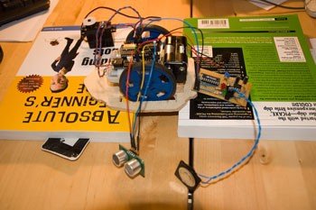
One part will be built round a solar powered motor. This is a Wilf Ritger design, and I think later became Solarbotics' Miller Engine. What you can see on the breadboard is the motor and motor driver on the left and the solar engine on the right. The motor driver has been tested using a 4.5v battery. the solar engine isn't working yet. I need to buy some better probes for my multi-meter from Maplin tomorrow morning.
The second part will combine Solarbotics motors and wheels with a PicAxe and some simple sensors. this will be my first PIC project, and I'm looking forward to starting that once I have the first part working.
The two brains will come together in one body, and that's the secret ingredient for the moment.