


Rampagebot V4 Project
This robot features the Arduino bootloader with ATmega168 microcontroller and motor control circuitry built-in.
A battery module plugs in through a stackable arduino shield compatible pinout.
The video to the left is a simple motion tracker device built around a Sparkfun Atmoic 6-DOF board.
A QT4 client was built on Ubuntu and PlayerStage allows you to communicate to a RRobot over Zigbee.
The server and client can run on a Gumstix Overo processor running at 600Mhz.
Currently, Ubuntu supports the ARM of the Overo which is a 600Mhz TI OMAP3540 processor. (This is the same processor as the Open Pandora and the Beagle Board.)
A Gumstix stackable shield is currently being developed. See picture below.
In addition, a Compact Flash sized FPGA Xilinx Virtex4 module can be added to the robot and can communicate with the Gumstix over a serial UART. This part has a 400Mhz PowerPC Hardcore processor.
In total this stackable shield will have over 2GHz of computing power.
600 MHz ARM Cortex A8 + PowerVR SGX530 GPU + 430 MHz C64x+ DSP + ISP (Image Signal Processor) + 400MHz PowerPC + ? (400Mhz max) ? (Xilinx Microblaze Softcore processor.
 "
"
Gumstix & FPGA Rampage Robot Module: This is the final revision of the top layer with notes documenting changes in the design process. This board is a collaboration between Pico Computing and Rampage Robotics. There are plenty of IO to extend to daughter shields. The Compact Flash header is designed for the Pico Computing E12 FPGA module as seen below.
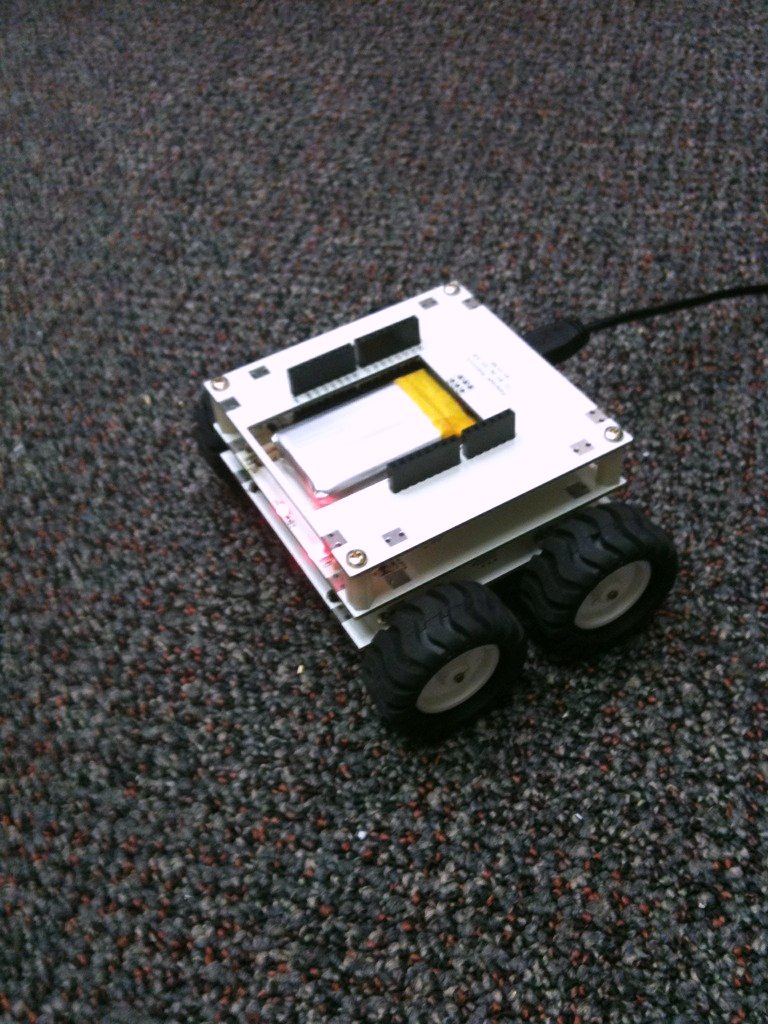
Rampage Robot V4 (Prototype): This is an example of an assembled unit with battery and motor modules.
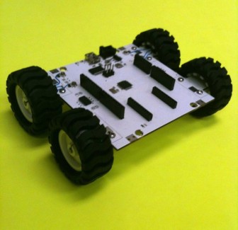
Rampage Robot V4 Motor Base: This is the top and bottom layer of the motor layer. An ATmega168 is connected to a USB-to-Serial converter allowing operation with the Arduino IDE bootload feature. Two Red and Blue status LEDs indication communication between the PC and robot. A Xbee connector also allows bootloading and remote reset by a built in header.
RIT Robotics Club Demonstration Rampage Robot Line Following from Jose Torres on Vimeo.
Additional information will be added soon. (Latest Update 2:00AM EST Sep 6, 2009)
Please view our website:
http://RampageRobotics.com
See us on Thingiverse:
http://www.thingiverse.com/thing:967
Board files will be released under CC BY-SA-NC license.
Information on new stackable modules and tutorials will be released in the next few days.
- CPU: Arduino, Gumstix Overo 600Mhz
- Operating system: Ubuntu (Linux)
- Programming language: C++, Java, C, Arduino ide