


[R.I.P.] YA2WDNSOSBBALABMHAMF
YA2WDNSOSBBALABMHAMF (Yet Another 2WD Not So Original Starter Bot But At Least Assembled By My Own Hands As My First) or just B4short,
--- a tale of many horrors, woes of a beginner & some reasonable success...
NOTE: Inverted video order, NOW the most RECENT is the topmost video.
April 2013:
- Due to popular request I've decided to add the proper name pronunciation for YA2WDNSOSBBALABMHAMF.
( see (I mean... hear) attached file above )
- Also made overall minor formatting/text tweaks throughout the whole post.
NOVEMBER 2012:
R.I.P. YA2WDNSOSBBALABMHAMF
It had a nice run, but what I suspect was a crippling solder joint problem led it to eventually to malfunction, so I "sent it to a farm upstate" to roll free in the meadows... no, actually I just disasembled it and scavaged its parts. But yes it was not working properly before that moment. However, it served its purpose, which was to get me started and show me that I could do something mildly operational. Thanks YA2WDNSOSBBALABMHAMF you'll live on in my <3
Objectives:
- Assert my skill level regarding the requirements of the world of hobby robotics.
- Get to know the arduino platform and mess around with general electronics.
- Being able to do hobby robotics at a self-satisfactory level.
Learning summary/acquired knowledge:
- General knowledge about the most common electronics components.
- Arduino platform + Arduino C (enough to get by and improve as necessary).
- Building electronic circuits:
--- dealing with electric noise using respective dampening counter-measures (caps, isolating prickly sensors in sub-circuits...).
--- ensuring there's a common GND (toasted 3 atmega I/O pins once by not having a common GND).
--- ATmega chips & standalone *duinos.
--- Basic soldering on perf boards (continuity checks after doing a bunch of solder points is a good idea).
- Can't abide the contact glue's smell but it god damn useful [it's holding my bot together :P]
- Scavenging for structural materials is awesome (CDs, toothpicks, drinking straws, cardboard, packing foam...).
- Assorted building tips (parts placement, materials, etc.) [alas nowhere near of becoming a mech engineer :P]
Failures:
- Getting the wheel opto-encoders to work properly, mostly getting a clean signal out of them, and/or debouncing said signal.
- Anger management (half success -- despite many threats I managed to keep the hammer away from my emerging bot)
- Time management... (to quite a while to reach "done" phase)
EDIT: August, 10th 2012
-----------------------------------------------------------------------------------------------------------------
- Replaced the ATmega328P chip with a ATmega8 chip.
- Added the bot's arduino C code to the end of this post.
- Main objectives achieved -- I consider this bot: 'proto-done'.
EDIT: July, 13th 2012
-----------------------------------------------------------------------------------------------------------------
Just added a new video of 'B4SHORT' roaming around happily around the house. Quality is not so good as usual (recorded w/ phone camera and by me), but I've fumbled a bit longer with the video editor this time, but don't expect to be dazzled :P
EDIT: July, 12th 2012
-----------------------------------------------------------------------------------------------------------------
Updated the main project photo to reflect the physical changes I made to the bot last night. Basically, I've mounted a couple of micro switches on an ice cream stick to serve as bumper switches. Also glued a sweetner dispenser lid as an extra support for the servo. I still need to improvise some kind of bumper that connects to the switches tabs and runs across the bot's width. So I guess I can say Phase 2: completed; whereas Phase 1 was: reproducible autonomous runs, (A.K.A. Collect underpants!) and Phase 2: completion of essencial hardware mounting. (A.K.A. ??!!? )
Phase 3: Pimp my ride!!! (A.K.A. PROFIT!) where I'll see what pins I have left and decide what to make of them. After that I'll just do some structural reinforcements/tweaks plus code clean up and I can consider this experiment completed :) Also I intend to replace the atmega328P with a atmega8 as soon as I get the ones I ordered.
EDIT: July, 7th 2012
-----------------------------------------------------------------------------------------------------------------
SPOILER: IT ROLLS, and even avoids some obstacles :P
So basically when I was testing for bad connections ('cold solder points') I actually found bad connections, but between some pins and the female 4P header on the L293D perf board.
Following that I've also realized how usefuless 9V batteries really are, I mean I new that their current output was typically meager but I was expecting it to be enough to power the *duino and hc-sr04. More so, I was using a couple of of 9V in parallel rated 300mAh each, so I was expecting to have a 600mAh output. But I guess printed rating cannot be trusted, and even more so in the case of cheap chinese batteries. Thus, I replaced the 2 parallel 9V batts for a pack of 6x AA rechargables, and kept the 4x AA rechargables I already had (for motors and servo).
All that entailed a few structural changes... and a few velcro strips (to keep battery packs in place), cardboard + foam sheet (a separator and bed for the perfboards) and rectangular piece of plastic (new mount for the hc-sr04 on the servo) and thus I arrived at the current robot configuration.
The tests show me what I was already expecting, bumper switches would be quite handy, I have already ordered a batch of them a few weeks ago... but if get impatient I might scavenge a pair of microswitches from a decomissioned pc mouse and implement the bumper sooner than later.
And for now I can rest for a bit during this weekend, bask on my mild success... and spam less of my frowns :| on the shoutbox :P So everyone wins! :P
EDIT: July, 6th 2012
-----------------------------------------------------------------------------------------------------------------
Ok, after a evening of more testing, and fuming fustration, I managed to at least assert that the connection to the HC-SR04 was to blame (in part) for things not working as they should. Since there's not much to go wrong with plain cables, the problem must lie at the connectors. My guess is at the 4P female header end, where I first put to test my (lack of) solder skills [see beggining of project] is the problem. Anyhow, replacing that connection with proper proper factory made cables (dupont-ed ribbon) things start working as they should. Well, at least when I have my original arduino UNO paired up with the L293D self-made perf board and the UNO is powered via USB (and the L293D board via batt pack regulated). [Also my parallel dual 9V batt 300mAh seems not to be holding up to the task, although theorectically they should, I guess...]
However, things go bad again when I replace the UNO by my self made *duino board. So, there's something wrong with my *duino and after double checking for solder bridges twice I could not find any... Thus while speaking to a friend of mine about such woes we started to suspect I might have the "opposite" going on ... cold solder? is that how it is called? that is... poorly made solder points were I allowed oxidation galore that now provides me with wonky contacts, thus causing variable effects... *sigh*. I think I would be better off starting another *duino board from stratch, that is, only after I do like a random solder maraton just for training purposes :/
EDIT: July, 4th 2012
-----------------------------------------------------------------------------------------------------------------
After around 2 stressful weeks of trying to put my wheel opto-encoders to work properly... I just gave up. In the meantime I managed to re-realize just how flaky is the physical structure of my bot and that's it's barely held together. Considering that I've re-adjusted the objectives for this project. So now they are: starting point experience in robotics, and make a reasonbly shambling obstacle avoidance bot.
Anyhow yesterday I've receive the dupont connectors so I at least I had a blast reducing the previous mess of wiring I had. That and some structural modifications I've made during the course of these couple of weeks made the bot look like what can be seen in the photo below: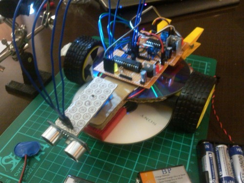
Added another CD disk that provides further support for the "neck" servo and the couple of 9V batteries that feed the *duino and sr04 circuit. A couple of laundry clamps that provides support for the 4AA pack and compensates for the previous front-heavy design.
Now I need to modify my perf-board circuits to accomodate more +5V power/GND connection points... I do hope the female headers that I've ordered arrive soon, otherwise I'll use more male ones for the aforementioned purpose.
EDIT: June, 18th 2012
-----------------------------------------------------------------------------------------------------------------
Just added (below at proper location) the TCRT5000-based schematics for the wheel encoder sensors I've built.
EDIT: June, 16th 2012
-----------------------------------------------------------------------------------------------------------------
As it happens upon the ressurection of my phone I found a video and a couple of photos that I thought were lost/corrupted/unsaved. Relevant to this post is the video (the 3rd from the top) that I post now. There I show 'b4short' running (alas still in circles) but I blocked it's path a few times so the servo routine can be seen kicking in.
Below you can see more clearly how scary and messy looking I've made it so that I could do the live ground tests.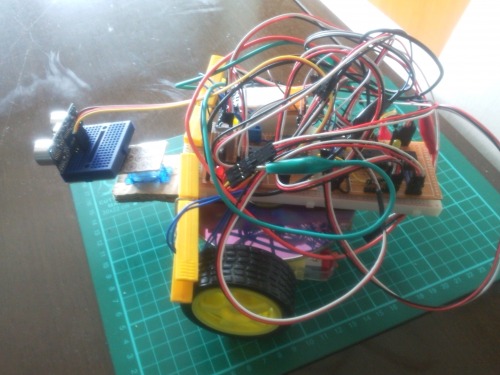
But fret not, in the meantime the monster above has been gutted and suffered some slight/moderate structural changes. Most of all currently my main concern is differing speeds between left and right motors.
With that in mind I'm exploring (trying to learn) wheel encoders and related stuff.
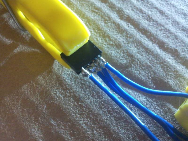
For that purpose I've made a couple of these below using some TCRT5000 sensors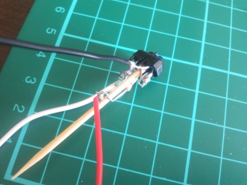
(yes, there's a toothpick there)
and then with some printed wheel disks glued on the inside of the wheels I've put the encoder sensors in place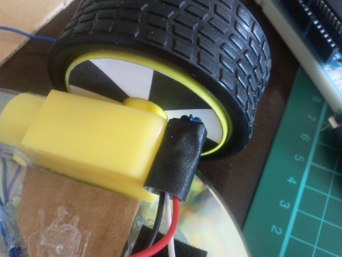
EDIT: Added the TCRT5000-based sensor schematics below: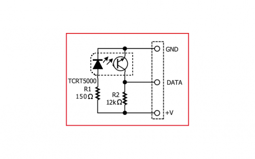
Now all I need to do, is actually learn how to make proper use of them. So, as soon as I can I should be hitting the forums whinning how complicated this is and how it makes my head hurt. (and yeah I just want to do single channel encoding which is more than enough for my purpose).
EDIT: June, 15th 2012
-----------------------------------------------------------------------------------------------------------------
OK. eagerness led me to make a first (and second & third) 'wet' test run. I've pile up things best way i could, resulting in an ugly mess of a bot.
1st run: fell apart while moving, crashed into the walls and THEN activated the servo routine. That was easily fixed, removed some delays from the code, increase the safe distance and problem solved.
2rd run: packed the jumble of wires a bit tighter and balanced the load a little better, applied some hot glue to better fix the battery pack 1. the second run is the DEPICTED one on the video, you can only see it running around in circles.
3rd run: the same as the 2nd but where I would block the sensor with my hand to make the robot break out of its circle motions. alas my old android seems to have only pretented to record the video, since it was nowhere to be found on the phone.
Conclusions:
- Structural capability of the bot needs dire review, reinforcement and or major revision up to a complete rebuild.
- I need to acquire female connectors so that I can make my own specified length connection jumpers and hence reduce the wire forest.
- Also need to add more sensors, either bumpers switches or short range IR (tctr5000 ???) because the bot also does not handle chair legs very well :P
- oh and compensate for the faster spinning right motor, I have to use encoders, right? :/ and then pwm signal "heyaa slow down boy" or something, right?
- and of course continuous code tweaking as I go, but that is somehow dependent on the previous structural considerations.
EDIT: June, 14th 2012
-----------------------------------------------------------------------------------------------------------------
Some connectors I was waiting arrived in the mail (alongside other goodies) so I took the chance to pretty up/finish the h-bridge board. Check below.
EDIT: June, 13th 2012
-----------------------------------------------------------------------------------------------------------------
Yesterday my lot of small perf. boards arrived in the mail. And considering today is an holiday around these parts I had the incentive I need to get on with my 3rd and 4th loooong soldering sessions. So basically what I did was:
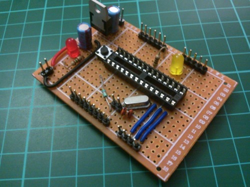
kariloy-custom-sort-of-duino w/ 5V regulator:
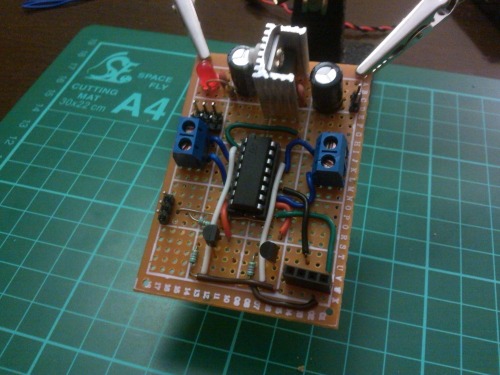
And Dan's h-bridge (https://www.robotshop.com/letsmakerobots/node/32462) with
OddBot's Vin/5V voltage regulator (https://www.robotshop.com/letsmakerobots/node/3880):
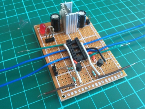
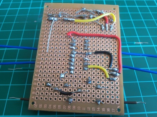
So basically I've perf-board soldered what I've already had breadboard implemented.
I still need to add more connectors (which I currently don't have in stock) to both of them. Anyhow a quick test seemed to show that both (independently) work as expected (although the kariloyduino is just running the blink sketch (need to delve more into the uploading stuff to the mcu whole business).
EDIT: June, 9th 2012
-----------------------------------------------------------------------------------------------------------------
Today (actually yesterday, but then midnight was upon me :P) was the 'use-the-soldering-station-for-the-second-time-ever' day.
Also I've re-mounted the sonar (now on a mini-breadboard) on the servo arm, and did some hot-glueing and velcro placement for battery pack attachment. The picture below (hopefully) subsumes most of what I've done tonight. Also on the right side you may notice another crummy video, for your horror, showing one of my latest "dry dock" test runs.
EDIT: June, 8th 2012
-----------------------------------------------------------------------------------------------------------------
After a week of long nights under the advisement of several people on the Shoutbox and a few more sources I've reached the following setup schema that:
- Eliminated the servo jitter
- (seemingly) eliminated the SR04 wild distance reports.
- Providing more current (through 2x 9V batt -- in parallel) for the arduino + sensor now segregated sub-circuitry also fixed the laggy/odd behaviour (when using just 1x 9V batt [300mAh]).
All seemed well until I decided to re-mount the sensor on the servo arm, then the wonky values (silly and even negative distance values) returned, almost looked like the sensor did not like measuring horizontal distances (tests were made with distance to ceiling). When I tilted it to measure distance to walls and stuff... kaput. First I thought it might be the cabling/connectors fault. After replacing them, the same happened. Also I mounted the sensor steady on top of the table so vibration would not interfere...and more of the same... so now I begin to suspect my HC-SR04 might be a bit faulty :| ... I've ordered another one, that should be arriving any day now...
more on my current woes can be read here: https://www.robotshop.com/letsmakerobots/node/32932
(@Blue Beta: I got my cutting mat today... hurray :P)
EDIT: June, 1st 2012
-----------------------------------------------------------------------------------------------------------------
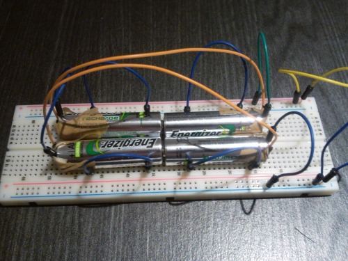
Ok, since long I've been "layman-y" suspecting of the 9V battery as being the root of many (we)evils!... Thus, I took it and the 9V->5V voltage regulator out. Just to test things out I've replace them with a flimsy improvised AA battery holder (while I wait for some proper ones arrive in the mail) as can be seen in the photo below. Overall, things worked out better for a little while, but then either due to current depletion and/or poor contact it went to a stop. Regardless, as soon I get my hands on proper battery holders I'll give this a try again, and using a proper voltage regulator too.
EDIT: May, 31st 2012
-----------------------------------------------------------------------------------------------------------------
Added, a 9V->5V voltage regulator in order to try and sort out the HC-SR04 queasiness. failed. Because I had a mess of several components spread over a few breadboards, I've re-done Dan M's H-bride + OddBot's voltage regulator into a "regular?" size breadboard still leaving half a board to lay the arduino one board on top.
Fur purposes of illustration the whole (reduced) mess can be seen below: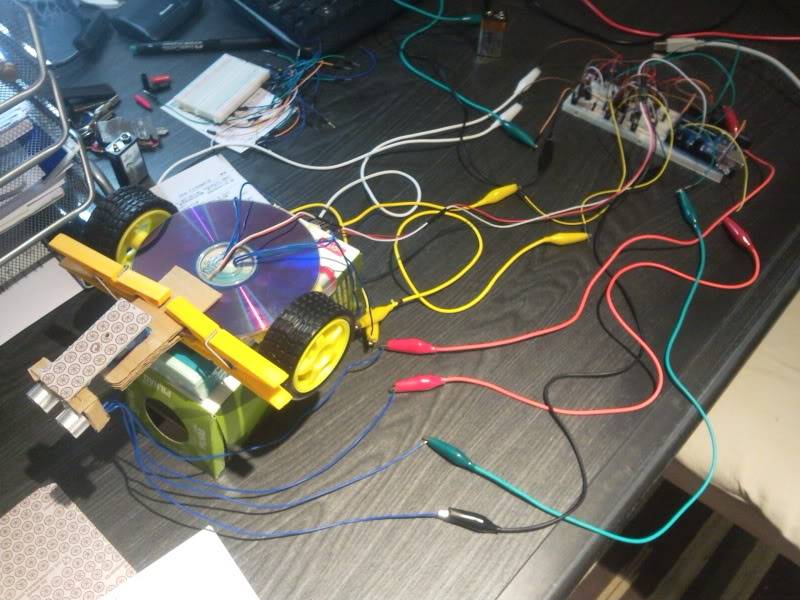
I had mild success running this thing, but only when powered through the USB->AB connection. Powering it with the 9V through the voltage regulator... sent the servo crazy locked into position zero and the sensor returning zero distance as well.
In the video in the link below it can be seen (barely, sorry for the overall quality) that it sort of works (should put colored stickers on the wheels), although most of the time you can't see the obstacle (my left hand) I put in front of the sensor, the response is slower (perhaps 5 seconds or more) than what would be desirable, but then again that may be a code issue, since I've only made a rudimentary draft to test things out.
http://s5.photobucket.com/albums/y153/Kariloy/Robotics/?action=view¤t=mildly-successful-run.mp4
EDIT: May, 28th 2012
-----------------------------------------------------------------------------------------------------------------
Finally got my hands on a couple of transistors and so I've (hopefully) implemented Dan M's H-bridge https://www.robotshop.com/letsmakerobots/node/32462 on a breadboard. At least while testing it standalone it seems to have worked as required/expected.
After that I've decided to sort of assemble the rest of the components for a basic dry-run and to test the code I've been writing in the meantime. During the it's assembly I've been forced into my first purposeful [I'm not counting all that solder I've melt when I was a kid just because it was fun] soldering job (yey!). Pretty shoddy as you can see below, plus I've managed to inhale some soldering smoke leaving my throat raspy for a while (hurray!)... :|
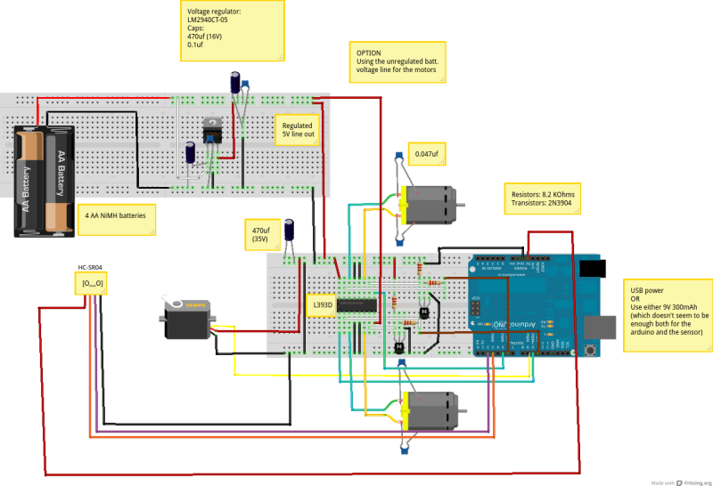
So in order to perform the quickest dry-run test possible I've set up my connections something like this:
WARNING: Shoddy image-editing below, plus "stolen" (I hope you don't mind Dan) material.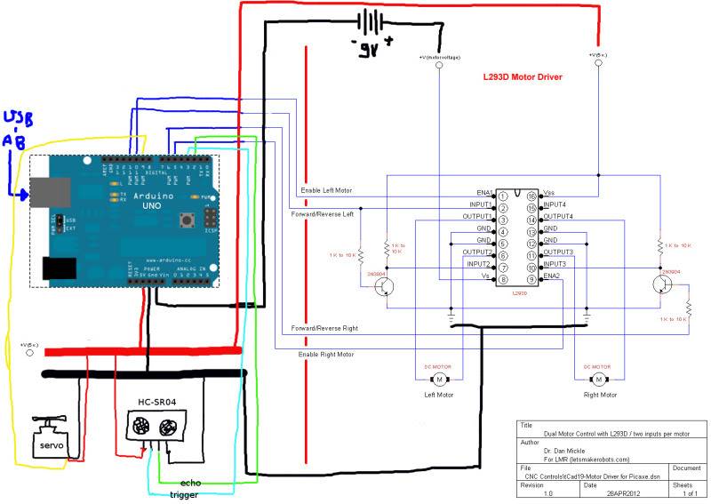
ALAS, the HC-SR04 ultrasonic sensor did not like my setup and besides reporting true (but with +- 10cms distance fluctuations) results when standing still (motors off), when the motors started (motors on) dry-runing (robot at top a pile of stuff so it didn't move anywhere) it would randomly (?) find invisible obstacles where there were none to be found.
My guess is that my amateurish power connections are the ones giving me grief over the SR04 false results :(
EDIT: May, 21st 2012
-----------------------------------------------------------------------------------------------------------------
Last evening/night I've done a little of VERY lo-fi poorman's cardboard engineering, basically I've added a cardboard support for the "neck" micro servo, and a cardboard housing for the SR04 sensor, connected it with a strip of harder cardboard. Hot-glue all around.
First steps:
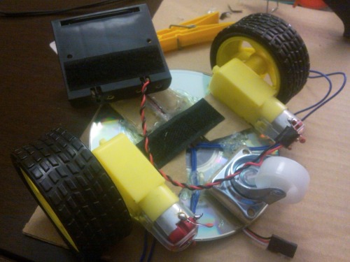
Well, finally I've started my first go at building an autonomous bot, nothing fancy, nothing original just something to learn to go through the ropes. I'm going for a 2WD design that according to the internet seems to me that is quite ubiquitous (and good for a beginner).
As of the moment (May, 17th 2012) basically I've only glued together a couple of DVDs to use as base (as suggested by generalgeek), and then also hot-glued a couple of geared DC motors and a 3rd idler wheel to it.
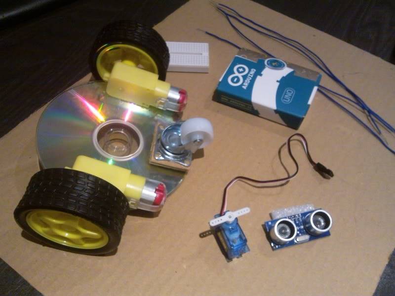
Component-wise I'm only waiting for a couple of transistors to build an H-bridge (as sugested on a Dan M's post).
While I wait for them to arrive I'll just scavenge some code and I'll toy around with it and learn how everything fits together, from the arduino begginer tutorial that I've already completed I think I have the general gist of how it works, still there is much to learn.
----------------------------------------------------------------------
The code that makes (made) b4short "tick"...
----------------------------------------------------------------------
#include <DistanceSRF04.h>
#include <Servo.h>


DistanceSRF04 dist;         // Define the "batvision" object
Servo neckServo;            // Define the Servo object


const int stopDist = 15;    // STOPPING distance (TWEEK THIS)

volatile int bumper_L = LOW;
volatile int bumper_R = LOW;

boolean started = false;

int distance;               // current distance to obstacle
int distArray[2];            // array of distances measured during a sonar sweep

const int corr = 195;       // cap the right motor's vel

int enableRight = 5;        // Enable/disable RIGHT motor
int enableLeft = 10;         // Enable/disable LEFT motor

int directionRight = 6;     // Direction of RIGHT motor
int directionLeft = 11;      // Direction of LEFT motor


void setup()
{
  // set the bumper switches
  //pinMode(4, OUTPUT);
  digitalWrite(2, HIGH);
  digitalWrite(3, HIGH);

  //digitalWrite(4, LOW);
  // pins for hc-sr04 Echo AND Trigger (respectively)
  dist.begin(12,13);
  // attach the servo on pin 9 to the servo object
  neckServo.attach(9);
  // set the wheel pins
  pinMode(enableRight, OUTPUT);
  pinMode(enableLeft, OUTPUT);
  pinMode(directionRight, OUTPUT);
  pinMode(directionLeft, OUTPUT);
  // set the interrupts
  attachInterrupt(0, hitRight, FALLING);
  attachInterrupt(1, hitLeft, FALLING);
  // ...start your engines...
  started = true;
}


void loop()
{
  // Have I crashed into something?
  if (bumper_L == HIGH && bumper_R == LOW)
  {
    reverse();
    delay(750);
    spinRight();
    delay(500);
    bumper_L = LOW;
  }

  if (bumper_L == LOW && bumper_R == HIGH)
  {
    reverse();
    delay(750);
    spinLeft();
    delay(500);
    bumper_R = LOW;
  }

  if (bumper_L == HIGH && bumper_R == HIGH)
  {
    reverse();
    delay(500);
    spinRight();
    delay(500);
    bumper_R = LOW;
    bumper_L = LOW;
  }

  // Let's see what's ahead and how far we are from it
  howFar();

  if(distance > stopDist){
    forward();
  }
  else{
    stopBot();
    lookAround();

    if(distArray[0] <= stopDist && distArray[1] <= stopDist){
      reverse();
      delay(750);
      spinLeft();
      delay(750);
    }

    else if(distArray[0] <= distArray[1] && distArray[1] > stopDist){
      forwardRight();
      delay(500);

    }
    else if(distArray[0] > distArray[1] && distArray[0] > stopDist){
      forwardLeft();
      delay(500);
    }
    else if(distArray[0] <= distArray[1] && distArray[1] <= stopDist){
      reverseLeft();
      delay(500);
    }
    else if(distArray[0] > distArray[1] && distArray[1] <= stopDist){
      reverseRight();
      delay(500);
    }

  }


}  // close loop() function


// are we there yet?
void howFar()
{
  delay(25);
  distance = dist.getDistanceCentimeter();

  if (distance < 0){                              // correction for negative distances
    distance = 666;
  }
}


// no way? jose?
void lookAround()
{
  int pos;
  for(pos = 30; pos <= 150; pos += 1)    // goes from 30 degrees to 150 degrees in steps of 1 degree
  {
    neckServo.write(pos);               // tell servo to go to position in variable 'pos'
    delay(15);

    if(pos == 45){
      delay(500);
      distArray[0] = dist.getDistanceCentimeter();
      if(distArray[0] < 0){distArray[0] = 444;}      // correction for negative distances
    }
    if(pos == 135){
      delay(500);
      distArray[1] = dist.getDistanceCentimeter();
      if(distArray[1] < 0){distArray[1] = 444;}      // correction for negative distances
    }

  }
  neckServo.write(90);                  // returns to looking forward
  delay(100);
  howFar();

}

// bumping action

void hitLeft() {
  if (started)
    bumper_L = HIGH;
}

void hitRight() {
  if (started)
    bumper_R = HIGH;
}


// You got'ta move it, move it...

void forward()
{
  analogWrite(enableRight, corr);
  digitalWrite(enableLeft, HIGH);

  digitalWrite(directionRight, HIGH);
  digitalWrite(directionLeft, HIGH);
}

void forwardRight()
{
  digitalWrite(enableRight, LOW);

  digitalWrite(enableLeft, HIGH);
  digitalWrite(directionLeft, HIGH);
}

void spinRight()
{
  analogWrite(enableRight, corr);
  digitalWrite(directionRight, LOW);

  digitalWrite(enableLeft, HIGH);
  digitalWrite(directionLeft, HIGH);
}

void forwardLeft()
{
  analogWrite(enableRight, corr);
  digitalWrite(directionRight, HIGH);

  digitalWrite(enableLeft, LOW);
}

void spinLeft()
{
  analogWrite(enableRight, corr);
  digitalWrite(directionRight, HIGH);

  digitalWrite(enableLeft, HIGH);
  digitalWrite(directionLeft, LOW);
}

void reverse()
{
  analogWrite(enableRight, corr);
  digitalWrite(enableLeft, HIGH);
  digitalWrite(directionRight, LOW);
  digitalWrite(directionLeft, LOW);
}

void reverseRight()
{
  digitalWrite(enableRight, LOW);

  digitalWrite(enableLeft, HIGH);
  digitalWrite(directionLeft, LOW);
}

void reverseLeft()
{
  analogWrite(enableRight, corr);
  digitalWrite(directionRight, LOW);

  digitalWrite(enableLeft, LOW);
}

void stopBot()
{
  digitalWrite(enableRight, LOW);
  digitalWrite(enableLeft, LOW);
}
Roam randomly navigating around obstacles by using ultrasound
- Actuators / output devices: 2 dc motors, 1 micro servo
- Control method: autonomous
- CPU: ATmega8-16PU
- Power source: 2 rechargeable battery packs: 4AA + 6AA
- Programming language: Arduino C
- Sensors / input devices: 2 Bumper switches, HC-SR04
- Target environment: indoor