


R/C Little-buggy
When my brother's R/C toy car's electronic was broken, he wanted to buy a more professional one to be able to control the speed and steering continuously. I checked the mechanic of the car and realized that I can build the whole electronic required to enable it to continuously change the steering and thrust of the motor.
Videos:
The first video shows Transmitter / Receiver testing. In the second video, before installing the roll-bar, a field test is being performed by my brother while I am filming! :)
The third video is a spin demonstration captured in HD. And yeah! We made the floor to be a little slippy ;-)
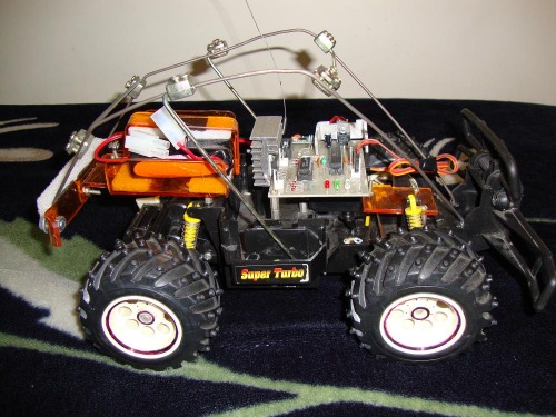
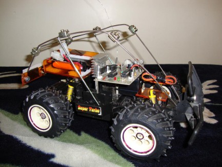
Fig.1 - The receiver board is mounted in the middle of the car.
Receiver:
The receiver was designed based on Atmega8 AVR micro-controller being clocked by an 11.0592 Mhz crystal. The schematic circuit is attached as "RCReceiver.PDF". To control the DC motor, a PWM signal is generated by u-C in "Phase and Frequency
Correct PWM Mode". Driver circuit is an LM298 which is able to drive two DC motors simultaneously. I used this H-bridge IC because I wanted to use the design in some other projects in which a differential drive platform is target mobile vehicle. To be able to change the direction of the motor, a Quad 2-input OR gate 74HC32 was utilized to change the direction of the motor rotation and stop it while the PWM signal is always generated and is available on the output capture pins of the u-C. To control steering, an standard servo was installed upside-down, see Fig.2 and Fig.3.
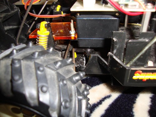
Fig.2 - An standard servo installed upside-down to control the steering mechanism.
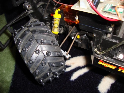
Fig.3 - Steering mechanism. Servo turque is applied to the left wheel.
For RF link between the receiver and the transmitter, I prefered to use RFM12 module from HopeRF which is an inexpensive reliable ISM band FSK transceiver module. It is available in different bands, 315/433/868/915 MHz. The modules I got were usable in 433 MHz ISM band. This band for this module has been proved to produce the maximum range.
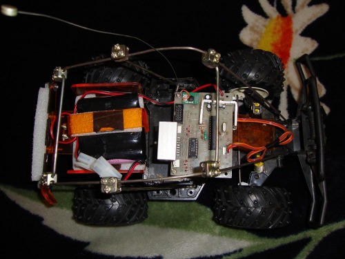
Fig.4 - RFM12 module can be seen on the top-left side of the board.
There are three LEDs on the receiver board. Red LED for power on, blue LED for RF reception signal and green LED for indicating of steering command. A 5x2 IDC connector mounted on the board to enable in-circuit programming.
Transmitter:
I didn't design a PCB for the transmitter circuit. I prefered to use a Vero-board and solder components on. For the case of the trasmitter, I found a used R/C box to put the board and all the other components into, see Fig.5 and Fig.6.
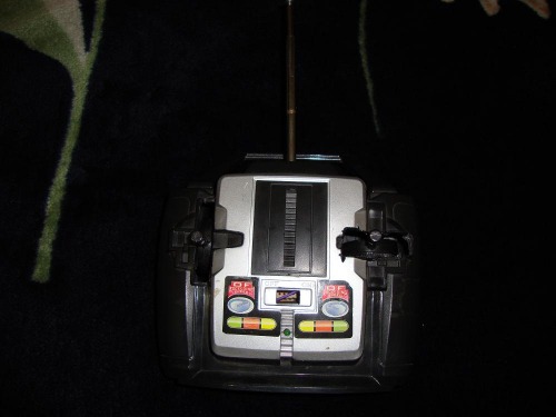
Fig.5 - R/C transmitter.
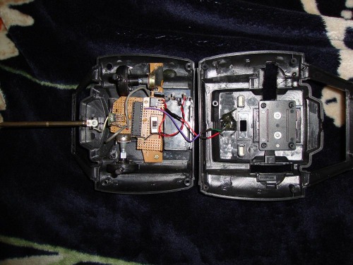
Fig.6 - R/C transmitter, inside the box. There are two potentiometer to command steering and thrust.
The transmitter schematic is attached as "RCTransmitter.PDF". The heart of the circuit is similar to the receiver baord where an Atmega8 and RFM12 module are connected the same way in the receiver. There are tow potentiometers to command continuous signal for steering and thrust of the motor. The internal A/D of the u-C reads these potentiometer positions, decodes into bytes and sends over to the receiver. I configured the modules to work at 4.8Kbps. There is a simple digital filtering algorithm which reduce the noise effect on reading potentiometers by averaging multiple readings.
Software:
Although I know that the board Arduino and its open source compiler made a great attractive to hobby robotics community, but because I was familiar with AVRs many years before the Arduino being introduced, I still would like to design my own AVR based controller boards and compile my programs in C with CodeVision AVR compiler. Unfortunately, this great C compiler for AVRs is not open source and hence requires a premium license. But there is a freeware version which limits the code size to 4Kbytes. It is not bad specially for small projects like this that transmitter and receiver HEX code size are both less than 2Kbyes.
R/C Car buggy
- Actuators / output devices: standard servo, DC motor with gearbox
- Control method: manual
- CPU: atMega8
- Power source: 14.8V Li-ion
- Programming language: CodeVision AVR
- Target environment: indoors, Outdoors