


PSU Bot
This is my first robot (actually I made one a few weeks ago that was not so good...just so I could see something moving--instead of just lighting up LEDs and such). I set out to gain understanding of a few things that I know will be necessary for my future robot building--fundamentals (Use of two seperate power sources, modifying servos, more soldering on a PCB (Ive done some in the past), making use of switches, unexpectedl...learning how to organize components in a small space, and other various things. Now for the details...
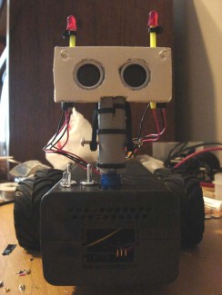
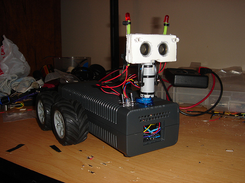
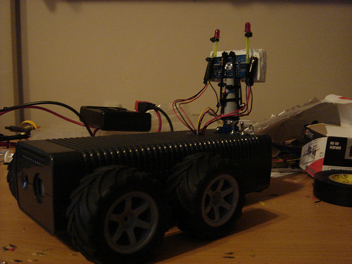
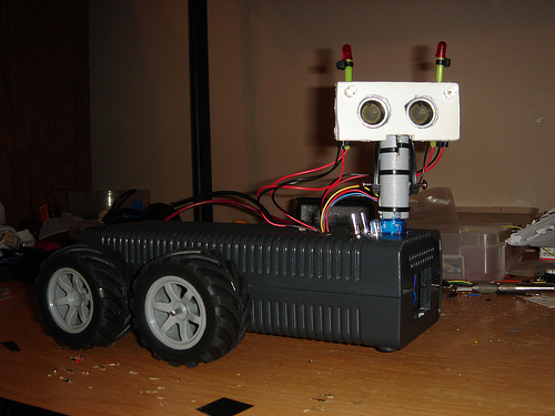
The chassis of this robot is an XBOX 360 PSU case (my old one died, I bought a new one, and uses the old case for this robot). I think it works very well as it is easy to drill through/dremel, its an enclosed case, and it is approximately the proper shape. The tires/wheels were on clearance at radio shack for $0.97. The 7.2V 1200 mA batter was also on clearance for $4.97 (regular price about $40.00). I believe these parts are made for an RC car that RadioShack sells...and perhaps this RC car product was discontinued.
What the robot will do:
1. Drive around aimlessly and avoid running into obstacles (via ping)
2. Two "antennas" will be attached to the head (not pictured above). Each antenna will have an LED attached to the end to indicate whether the robot is about to make a left or right turn.
3. A photocell will measure light. When the lighting becomes too low, the robot will turn on his head lights...even though he doesn't need them.
4. Perhaps for more fun, he will occasionally stop and dance a little jig for us. Eh...I changed my mind. I don't really feel like doing that with this robot...he doesn't even have any arms...I'll save it for a future bot.
5. He will do nothing useful except make myself and (hopefully) others laugh.
Current Problems:
1. A while back I modified two Traxxas serovs for continous rotation by simply drilling out the "final" gear so that it would not rotate the potentiometer. This worked very well and when I told the servo to go to 90 degrees (center), the servo stopped very well. However, the potentiometer in these Hobbico servos are VERY sensitive. Simply drilling out the gear that rotates the pot was not enough, and after only about a minute of rotation, the servo would no longer stop when told to go to 90. So, my (incorrect) solution to this problem was to simply detach the servo (in the code) when I wanted it to stop and then reattach it when I needed it to start again. This works fine--but only if the servo is powered via the 5V pin on the arduino. I tried this yesterday with the servos being powered by the 7.2V battery (5V through a 7805 Voltage regulator), and the servos do not stop when detached. They continue doing whatever they were doing until I reattach them and tell them to do something different. I'm sure someone here can tell me why it does that...and that I wasn't being all that brilliant trying to stop the servos with myservo.detach().
UPDATE: 19 July 2009
I found the solution to the problem above. I had not been grounding the separate power source circuit to the Arduino. You all probably simply assumed that I had done this because apparently it is well known that you have to do that. Now I know.
Some photos...
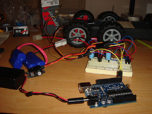
ABOVE: Separate power source test setup (before I learned that it must be grounded to the Arduino).
I might have a video up soon. The servo that turns the head has a pretty weak case and it somehow just popped open. I don't think its actually broken though...luckily.
Avoid object via ultrasound, indicate turn-direction with two LEDs, turn on its "head lights" when it enters a dark area, (Possibly RC/autonomous in the future)
- Actuators / output devices: 2xHobbico CS-61 Servos (modified for continous rotation), 1x Hitec HS-50 Servo
- Control method: autonomous
- CPU: Arduino Duemilanove
- Power source: 9V for the Arduino and the Ping))), 7.2V 1200 mA for everything else
- Programming language: C
- Sensors / input devices: Parallax Ping)))
- Target environment: Indoor (carpet or hard floor)