


Protobot - First robot project
Updated with a 2nd video! Code is now uptodate and can be found at: code.google.com/protobot.
Introduction
This project is all about details. If you think its a waste of time to sit all night debugging a sensor to get that correct reading you want. Well, then this project just isn't for you. I began working on my two wheeled balance robot in the beginning of June – and the 14th of August was the first time I managed to make my robot balance on its own for a time over 10seconds. If I had to guess I'd say I've used around 150 hours on the project, but that estimate is probably completely wrong. During the time I've worked on the robot I've also had other things to do and I've waited for parts ordered online, so the timespan isn't representative for how long it takes to build one of these things. Nevertheless, on a project where details matter its extremely important to understand fully what is going on, to understand why the robot behaves in a certain way. Otherwise debugging will prove to be very difficult and time consuming. Therefore, I'm certain of that taking your time will prove to be more meaningful, rather then rushing ahead and skipping the basics. Eventually, this has certainly proved to be one damn learning full process and I'm proud to say my first robot was a two-wheeled-balance-bot.Parts & Construction
This is a list elementary the parts I've used for making my bot and some commenting on how.
Arduino is the Microcontoller I've used. If I had been more experienced I'd probably just have programmed an AVR-chip, but since this was my first physical computing project the Arduino proved to be a very good developing platform.The Arduino IDE is abit simple and may lack some common futures, but it makes a good starting point. Changing to something different can prove difficult and confusing.
Sparkfun's IMU Board - ADXL320/ADXRS401 board including the ADXRS401 gyroscope and the ADXL320 from Analog Devices work as sensors on my robot. The gyroscope measures angular velocity while the accelerometer is able to very accurately detect tilt to a fraction of a degree. It is very important to pay close attention to these sensors. 1° degree is enough to make your robot tip over and loose balance. With the help of TeleFox I was able to learn how to use this hardware.
35:1 Mini Metal Gearmotor from Pololu are used to drive my robot. These are very good 6v motors. They are stable, quick and built with a quality gear. In v.2 of my balance bot I will change for bigger motors, though. As they are just barely strong/fast enough to do the job. This is of course due to the size and weight of the robot, not due to the motors.
Battery;
1000 m:Ah 7.4V Flightmax high discharge Li-Po battery is currently used to fuel the motors. I plan to use a 2200 m:Ah version, but I don't have the correct plug yet. Until recently I did use a 6.0V 2300 m:Ah Ni-Mh pack, but the extra volt and amp was needed to give the motors enough punch.
2300 m:Ah 6.0V Ni-Mh's are used to power the board and sensors. This is of course not good solution as the Arduino should have around 9V.
Pololu Qik 2s9v1 Dual Serial Motor Controller was used until recently when I by a mistake sent some high volt in the wrong channel and partly destroyed the chip. As a result I built a simple motor driver(from memory :p) using two SN754410NE H-bridge connected in parallel. This is providing bidirectional control over two motors using four PWM Pins on the Arduino and the combined chips have a 2A rating.
Wheels consist of two very light foam wheels used on RC airplanes. These have 7cm diameter and replaced some smaller Pololu wheels I was using earlier. The bigger diameter gives me a nice balance between force-at-wheels and speed.
Other parts: A decent amount of basic electronic components; potentiometers, resistors, capacitors, LEDs and lot of wires. A breadboard and some Polymorph also came in handy. Construction was made of thin sheets of Plexiglas and some nuts & bolts.
Future upgrades/v2 include: 19v Pittman Motors, 2x packs of 11.1v Li-Po batteries, new motor controller, remove Arduino and replace with ATmel chip to create a more permanent solution. Also; distance sensors(Maxbotix LV-EZ1 and a Sharp short range IR sensor.), xbee modules for remote control are in the planning.
Theory
The theory of balance is both simple and advanced. The idea is that we get some input from a sensor, we then run the input through a formula which calculates the tilt. Based on amount of tilt we send a amount of volt to the motors.
Knowing the angle of the robot lets us calculate torque applied by gravity using the following formula; mass * length * gravity * sin(degree) = Torque in Newton meters. Knowing this gives an indication of what kind of torque we need to counter the falling robot. So torque applied [Force at wheels * length * cos(degrees)] has to be bigger than the torque applied by gravity to overcome it [mass * gravity * length * sin(degrees)].
That was the simple part. What makes this process of balancing all hard and time consuming is the problem with reality and our model in general. Getting an exact point of balance using one sensor might not be as easy as first thought, and therefor there is no simple way of knowing the tilt. Combining several sensors to get exact readings of the robots position relative to earth is essential. This adds more theory or mathematics to the project through the use of filters. Filters combine two or more sensors, remove spikes caused by electronic noise, and as a result you'll get an estimate on a angle. The correctness of the estimate is on one side affected by the hardware in use – and on the other of the filter. One common and relatively advanced way of doing this is by the use of the Kalman filter. Already used on the in the 1960's on the Apollo, the Kalman filter has proven to be good both for space shuttles and balancing robots. You could also combine a couple sensors and calculate the average and call it a filter. This would probably be better then just relaying on one input, but not as good as more advanced options. As a final result is the stability of your platform.
On my robot I've implemented one version of the Kalman filter, which resulted in a very stable platform with an awful drift. I've used a large extent of time trying to find the cause of this without luck. So in the current codebase I'm using one part of the Kalman predictions for my angular velocity sensor and a unfiltered accelerometer for tilt calculations. These inputs are then combined in a PID, resulting in a platform which in its current state can balance for around 3 minutes. After that time irregularity in voltage will cause the platform to start drift. But that is in reality a hardware issue.
Issues and progress
- I've tested my sensors and learned how to use them.
- I've tested DC motors and learned how not to use them. Result gave alot of new knowledge made me order some different motors.
- I've tested the IMU board and learned slowly how to use it. I've realized that this is the place where I lack the most knowledge and where I'll have to invest the most of my time for understanding how it works.
I've built a small robot while testing sensors and motors using polymorph as a chassie, but it reminds me of the ugly duckling so I wasn't very interested creating a robot project for it. It didn't really deserve the attention. I'll add a photo just for the fun of it, though.Robot is now taken apart for parts (22/6-09).- I've built the chassie for my first robot. Added about 50% of the parts - and 20% of the wires :p
Do more research related to the filtering the data from the accelerometer and the gyroscope. I'll create a list of links for people interested in reading more at the end of this post.Find a easy way to build the robot platform. I've seen its popular to use a simple Plexiglas solution which indeed look pretty nice as well.DONE (22/6-09)Update this page with my progress on the robot.Test the motor controller with my new motors (22/6-09)- Fix drifting error. This is probably created due to acceleration and no velocity checks.
14th of August was the first time the robot balanced for more then 10 sec. Shortly after it broke the 1-2-3min mark.
16th of August; found issues related to power supply. Irregularity in volt due to long power cables and dropping volt after time of use causes the robot to drift. One problem is that the zero gravity spot on the accelerometer will fall. Solution is to rework the cables and use bigger batteries to be able to provide a stable volt over time. And try to update those kind of sensor related details dynamically and not hardcoded.
UPDATE Monday June 22:
This is more of picture update. I havent had much time lately to do build. work work work ... boring. But yesterday I had a few hours to create some parts and this morning i was able to assemble a prototype. I decided to go with the plexiglas solution. Found some fairly cheap A4 sized plates at a local store. My general idea is that the plates are assembled in layers - and adjusted with nuts. This makes it fairly flexible and easy to take apart if needed. Lets look at some pictures:

This is after the first time I assembled the structure just to see if the parts fit. As you can see I have it all put together in a very simple way.
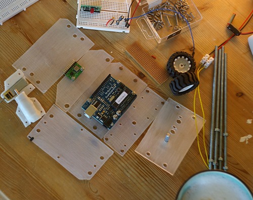
Here is after i polished the parts with some sandpaper to get a smooth surface. Adds a cool effect to it instead of the glossy Plexiglas which will get scratched sooner or later anyway. On the left side you can also see my custom motor mounts made out of Polymorph. And the right corner shows my morning coffee .. mhm :)
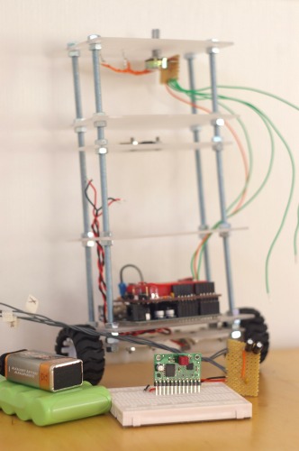
The assembled protobot with with its parts in front.
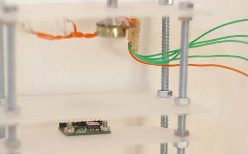
Just a close up of the sensor and potentiometer. Will be interesting to start testing the sensor when assembled on the robot. But still got some things that have to be done first. Thanks for watching.
UPDATE Tuesday June 23:
Small update this time. Just adding a few photos with the assembled bot and all the wiring. Put the batteries at the bottom of the bot so the motors get a easier job adjusting the balance. Now its time to start the programming :)
UPDATE 16. July
God, almost a month has passed since the last update here. Not good. I've been busy finding a new apartment, enjoying the norwegian summer, and working of course. Neither the less I've done some progress on this robot. It's going forward, slowly, maybe, but still - forward.
This time I've decided to add a very bad video. I think it's probably a good idea to show something in live motion. Since I dont have a video camera I've used the built in webcam from my MSI Wind. Now that is crappy, but wanted to add this video to show some drifting issue I've had on my robot.
Anyway, lets see what I've done since last time I published here.
- I've programmed the robot a few times with different codes, approaches, solutions. The code I'm using now, and which I will continue to work on, is heavily borrowed of open source implementation of similar projects - and especially when it comes to the Kalman filter. This is commented in detail in the source code of the project avilible at code.googel.com/protobot. I've tried to add easy to read comments the source where needed so it should be fairly understandable even for the the beginner, but its all still abit messy.
- I've used alot of time to understand how the different concepts of physics relate to each other to be able to create a stable platform. Yes, I know its drifting and falling over after a few seconds, but the robot seems pretty stable. And I'm sure, once I get a good balance algorithm going, it will be stable.
- There have also been some hardware changes. Due to the small wheels I had earlier, and the rather low RPM from the motors, I was having a hard time gaining enough speed to adjust my balance. So yesterday I bought some RC flight wheels with a bigger diameter and glued them on some pololu wheels so mounting them to the mounting axel should be easier. Bigger radius on wheels give me more speed (thus less force). As the motors I got had a good torque(0.002548 kilogram meter torque, to be exact). It was no problem to add bigger wheels.
So, thats about it. Think I add some more details and comments tomorrow, as now I'm to tired to think or wright anything sensible.
Reference and general links to similar projects and resources for the theory.
17th of August
Tried to update this post abit, will add another video once its uploaded. One month without internet and counting is forcing me to use internet cafees for this. Slow uploading ...
18th of August
Faster uploading at the University let me add another video. This one is abit longer and you can see the robot keep balance for good over a minute before it drives into my sofa :p I did also update the codebase on Googlecode for those of you who are interested. It's really nothing special to see, but gives an idea what lies behind(link: code.google.com/protobot).
19th of August
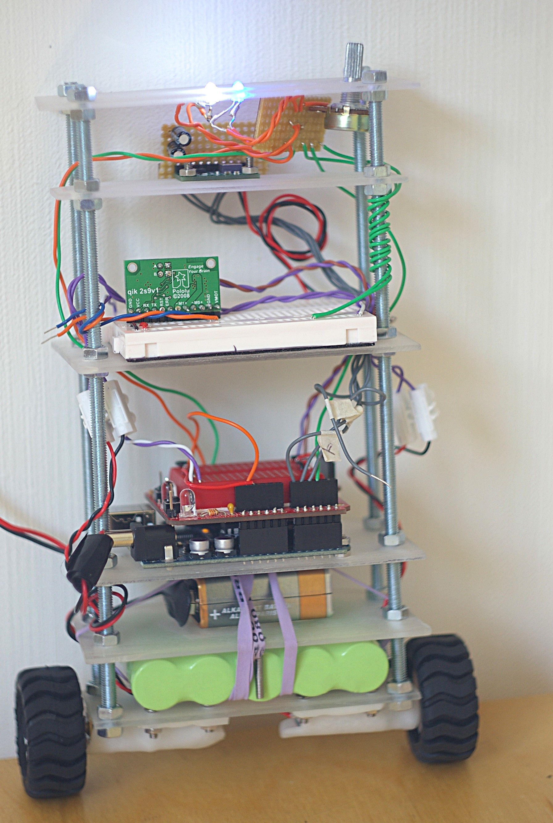
Added a high resolution photo showing the robot from new angles. I have also ordered a great deal of parts from a sweedish supplier(electrokit.se) for version nr.2. I did do some late night research regarding sensors for my second bot, but have not come to a final conclusion. I was thinking of buying latest ADXRS614 with 50'degrees/s maximum rate gyro together with a ADXL213AE +/-1.2g accelerometer. Both sensors focus on high precision, rather then wide range. The question is if they are too sensetive for a robot like this. Suggestions are very welcome.
Theory
- Kalman Filter Made Easy
- What is PID stuff, anyhow?
- Kalman filtering of IMU data
- Jordi Muñoz Kalman implementation in Arduino C
- The Kalman Filter
- Another document on balance filter
- Kalman filter for idiots
Similar projects
- myDanceBot
- How a Kiwi Built an Interactive Vision Guided Robot
- nBot
- Balancing Robot Project - "Bender"
- Segwii
- Daniel Bauen Balance bot
- GyroBot
- Links to other self-balancing-projects
- Analog Balancing Bot
- Equibot
- JOE le pendule's bot
- Balancing Robot
- Segwii
- b3r1 - Google Code
- bla repository » Archive » Inverted pendulum, balancing robot
- generation5 - Legway: Building a Self-Balancing Robot with Standard Parts
- http://www.geology.smu.edu/~dpa-www/robo/nbot/bal2.txt
Balance
- Actuators / output devices: 35:1 Mini Metal Gearmotor
- Control method: autonomous
- CPU: Arduino Duemilanove
- Operating system: Linux
- Power source: 7.4 Li-Po and 6.0V Ni-Mh
- Programming language: C
- Sensors / input devices: IMU Board - ADXL320/ADXRS401
- Target environment: indoor