


Project Test Chassis
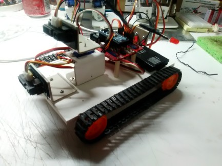
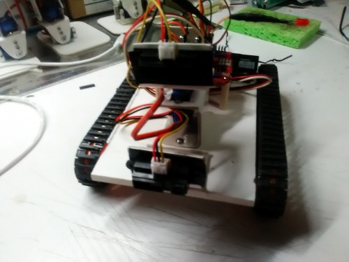
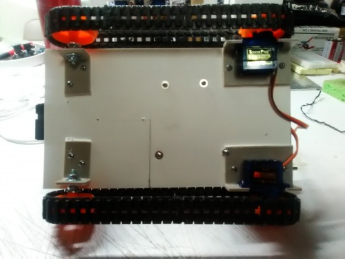
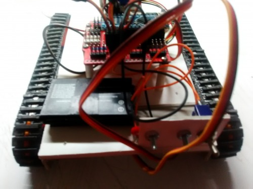
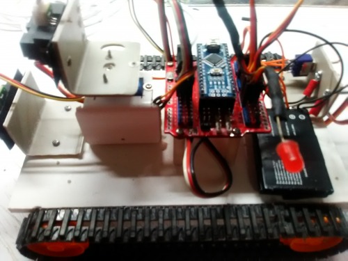
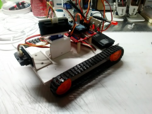
In the quest to build a robot that provides a function I decided to try and build a Floor Sweeper. I knew that building this would be a challenge. The biggest challenge I would face is how to navigate correctly and then how to cover an area without missing areas. The Roomba does not use a pattern to vacuum it is like all over the place and I can see where small areas would be missed. So how do we do this and not miss an area. I was watching a video of a House cleaning robot and a light bulb lit up. The idea I came up with was to handle everything in 90 degree angles as most room that I know of are square unless you live in a dome or the turret of a castle. Next I decided that I would do everything starting from the left going to the right. Okay, that is all fine so now what about a chassis or something to use for this test. Well, I thought I would use Wall-E but there was a problem, Wall-E's sensors are mounted in his head so it would detect object before it would detect the wall. I needed something that was low to the ground and could easily fit under a chair or table. Well Wall-E was not going to do that and my Biped were not even a thought. I decided I needed to build a test chassis that I could easily mount sensors on and take them off so that testing would be easy. I then was thinking of the drive train and what would work best. Wheel are great but small objects can get under a tire and bind it up and stop it. The next obvious choice would be tracks. I had purchased several sets of the Tamiya track kits at one time, I had found them on a site that was going out for $4.99 each so I bought like 6 sets for future projects. So now what will we use to drive them. Geared motors are great but then we are adding a motor shield and I knew I would be needing a sensor shield. The choice was easy, I would use servos to drive the tracks. No problem I have many of the little towerpro sg90 servos, all I had to do was convert a couple over to continuous rotation. Next was to interface the servos with the plastic wheels for the track system. I cut the servo horns down to fit within the wheels, centered them and used some 1/4" self tapping screws to attach them. So we now have a tracked chassis that can be used to test a wide range of sensors. I am using an Arduino Nano with a Sensor Shield, it runs on a 7.2v 800 mha battery pack. The batteries I used were from a old cell phone. I have two Sharp IR Distance sensors mounted, one is static at the from while the other is mounted on a servo so it can rotate. I knew if I could get a test chassis to do what I wanted that creating a larger chassis with a broom/Vacuum mounted would be easy. I first tested the chassis using ultrasonic sensors and they failed and were no were near accurate enough to do what I wanted. I then tested out the Sharp IR distance sensor and it work great and had very minor issues. The first step of the game was developing a pattern that the chassis would follow. After a lot of trial and error I was able to time the servo movements to do just what I wanted. The chassis would go forward until a distance was detected and then stop and then turn right and then go forward and then turn right and go forward until a distance was detected, it then repeats the same action but going left. Next issue was how do we know when the bot has finished vacuuming an area or do we just let it run forever. Well if every time we start from the left and move right when it reaches the furthest right there will be very little distance between it and the wall. So I added another Sharp IR sensor and mounted it to a servo. The second Sharp IR sensor check right to left for a distance level. If the chassis right side is close to a wall then the second sensor picks this up and turns the bot to the left (away from the wall) and goes forward slightly and stops. At this point the job is complete and a Red LED comes on to shows us it is finished. Below are some more detailed pictures of the chassis. The entire chassis took about 6 hours to complete. The software side took a couple hours and I am still refining it. I will be posting a video after some more testing and then I will be moving onto the full size chassis and designing a broom/vacuum.
After doing some more testing for when the vacuuming is complete I came across the following situation.
So lets say it is doing its job and is either under a chair or table and it does a right measuement to the wall.
The wall is not what it measure, it happens to measure the leg of a chair or table.
So what I did to correct this is to have it after the initial measurement move forward slightly and measure again and if it is still too close then move slightly in reverse and measure again. If either the forward measurement or reverse measurement are greater than the distance allowed then we know that it is the wall is not what we are measuring. If all three are less than or at the limit of the distance allowed then it is a wall and the job completes.
UPDATE: 2/3/2018
Working on detecting object/obstacles faster I have been very creative and come up with a way that does a constant Left/Center/Right distance detection while the bot continues to travel forward. At the same time it is very accurate in detecting the Min. distance to an object/obstacle and is able to quickly made a judgement and turn to avoid the object/obstacle.
After designing a way to quickly detect object/obstacles on the fly I then had the idea of what about a maze solver. So using the same object detection as above but changing how it turns based upon angle of detection the bot is able to quickly solve a maze without touching a wall. My testing was done using some boxes and books. I am now going to create a small maze out of cardboard and will post a video of it in action.
Navigate via IR Distance
- Control method: autonomous
- CPU: Arduino Nano
- Programming language: Arduino