Project: RobotShop Rover - Development
The RobotShop Rover was largely created as an exercise in integration and when it was first released in 2009 there were not many commercial Arduino-based mobile rovers on the market. We wanted to make a mobile platform which incorporated both drive and servo motors, sensors, and was programmable using an Arduino. We also set out to keep the retail price between about $200 to $300. A lot has changed since then, from the way we develop projects / products, the tools and procedures we follow, as well as what we're able to develop internally. Technology and product availability has also changed a lot as well.
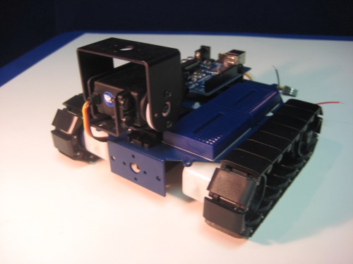
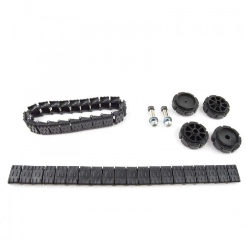
In order to keep the retail price down, we opted to build a small desktop robot that would be able to roam indoors on tabletops. To keep things simple, we only considered a single drive sprocket and single idler sprocket system which was readily available on the market. A programmable tracked platform that could accommodate a variety of sensors and even a gripper seemed to be ideal, and tank tracks seemed more aesthetically pleasing (as well as being more rare and potentially more desirable) than two or four wheels.The Johnny Robot tracks were quite nice and included the tracks, sprockets and hardware and were directly compatible with SolarBotics motors without the need for an intermediate hub.
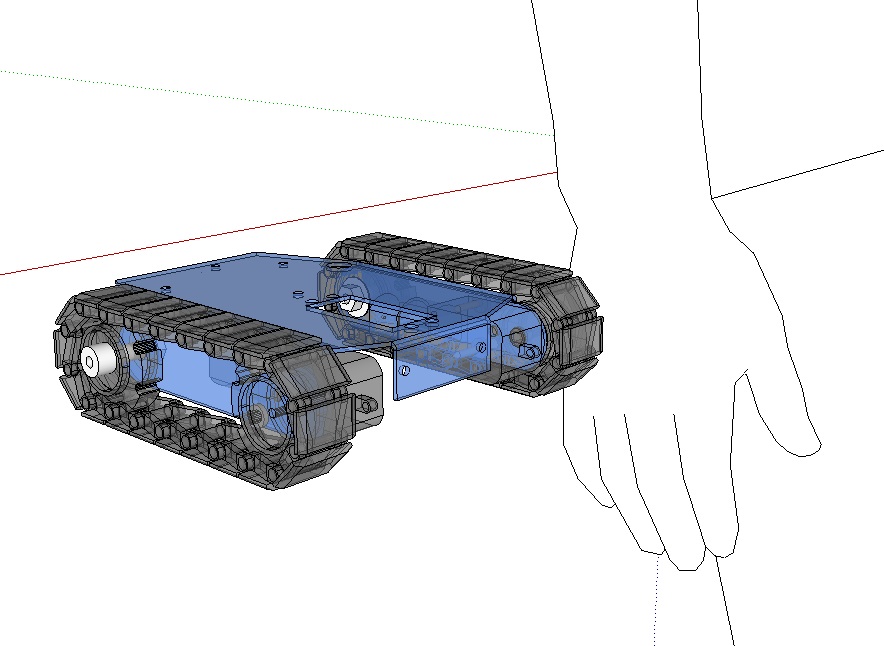
The first step was to dimension the frame based on the tracks and motors and make a mockup in CAD (Sketchup in this case). The frame needed to accommodate the motors, tracks, an Arduino Diecimilla, a battery pack, a servo, a sensor or two, a servo-based pan/tilt system as well as leaving space for prototyping. A bent piece of metal seemed like the ideal solution; the motors and tracks could be mounted on the sides, while the top and bottom provided ample space for all of the other parts. Aluminum is also pretty hard to bend and break, so it would make for a robust design.
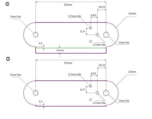
We had the tracks and motors in stock and it was easy to get the dimensions in order to do a quick prototype of one side. Since the design was quite straightforward, it was easy to cut out using heavy duty scissors / band saw and drill holes in the right locations (saved quite a bit of money at the time rather than having a company create a prototype).
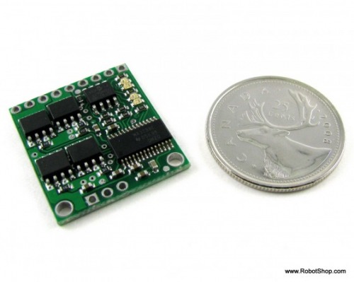
The next step was to choose a motor controller based on what was available at the time.
- The suggested voltage input range of the motors was 3V to 6V.
- There was no mention of continuous current, though the stall torque at both voltages is provided was 400mA and 700mA. If we take 25% of these values, the continuous current can be approximated at 100mA to 175mA. To be safe we can take the larger value.
- An Arduino microcontroller has many different pins including serial, PWM, I2C, analog and digital, so this would not be a limiting factor and we could choose a standard motor controller with almost any input.
- Our little rover would be using two identical drive motors, so we can use a dual motor controller.
Looking at the Brushed DC Motor Controllers Comparison Table, several motor controllers fit the criteria:
- RB-Dim-19 (6-18V, 5A, dual. Analogue and Serial interfaces with many safety features)
- RB-Pol-16 (1.5-6V, 5A, dual. Low cost controller with serial interface)
- RB-Pol-22 (6-16V, 9A, dual, PWM interface)
- RB-Spa-397 (5-16V, 2A, dual, serial interface)
- RB-Cri-15 (6-58V, 10A, single, PWM)
- RB-Cri-14 (6-58V, 10A, single, PWM)
- … and many more.
There were a variety of other motor controllers which met the criteria above which would work as well. In order to reduce this list, cost and features would need to be considered. For example, there was no need to consider a high current (10A) motor controller which is understandably more expensive than a 5A controller. We could also eliminate all single motor controllers since two single controllers almost alwasy cost more than one dual controller. The one controller that stood out from the rest was RB-Pol-16 because of its lower voltage range; this means that should we decide to power the motor at 3V, it would fall within this controller’s voltage range. The other controller of interest was RB-Ada-02 (discontinued) because it was made specifically for the microcontroller we selected (i.e the Arduino Uno) because of its shield format. However, the one downside to RB-Ada-02 was that no additional shields could be installed afterwards. The Pololu dual motor controller was ultimately chosen because of its lower voltage range and price. We're happpy to report that lots of motor controller shields have since been released.
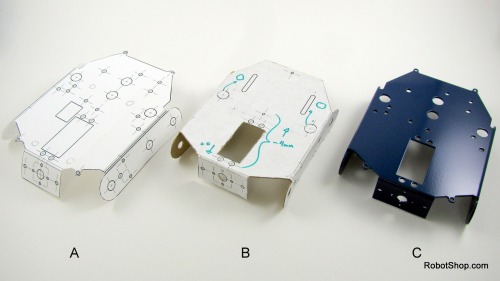
So far we had the motors, tracks, microcontroller (Arduino Diecimilla at the time), the motor controller and an idea of the frame. A basic sensor everyone used was the Sharp GP2D12, so cutouts were made at the front of the rover in order to easily mount it. Last would be room for a servo or pan/tilt. A few iterations more and a bunch of cardboard prototypes to double-check dimensions and appearance, and a final design for the frame was prototyped. A few modifications included adding the Lynxmotion SES patterns to the front, holes to mount the Parallax Board of Education (which turned out to fit quite well), as well as holes to pass wires and holes to add standoffs for a second level.
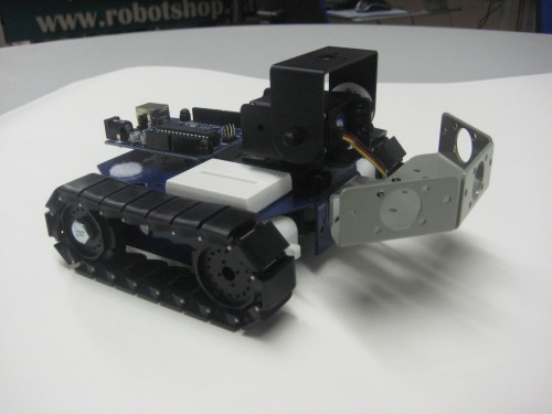
The SES pattern at the front meant any Lynxmotion SES brackets could be added, and at the time, the Robotics Connection multi-sensor bracket was a good fit:
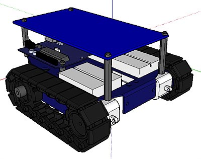
We have still not released an officialy second level to the platform, and likely will not do so, but it's easy to take a rectangular plate and add four holes. Customers have made their own variants based on their projects, though the basic platform has quite a bit of space for protoyping (three small breadboards).
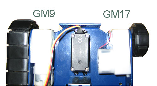
A decision needed to be made as to which of the two motors to select for the production rover.The GM9 from Solarbotics can be seen on the left while the GM17 is on the right. It was a bit of a toss-up but the GM9 seemed to have a better fit / finish so it was ultimately chosen.
The next question was how to power it all. One battery is always the most elegant solution, but since the Arduino needed at least 9V while the motors needed ~4.5V (and would not work efficiently if we applied 9V), we would either need a regulator or a two battery solution. Since the main power was to come from a 4xAA battery pack, the easiest option was to use a 9V battery to power the microcontroller. For commercial products these days, it's quite a bit better to be able to allow customers to use just one battery and charger for a robot.
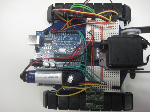
Quick and dirty wiring to make sure it all worked:
A few other views showing how easy it is to mount other boards such as the Parallax board of education and the Basic X development board. The Lynxmotion pan/tilt also have the option of adding a nice gripper, and the weight of the robot means you don't need to worry about picking up an object only to have the robot fall over.
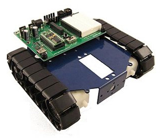
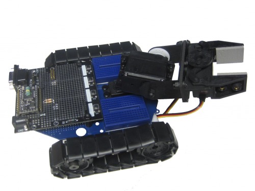
So, this is some of the rationale and thought processes which went into the first RobotShop Rover project which is still around today. The success of this platform led to the development of the much more integrated DFRobotShop Rover V1, V1.5, V2 and the upcoming V3. As you can see, it is possible to develop a commercial robot relatively inexpensively if you take the aproach of integrating existing products rather than developing them all from scratch. The cost of developing this rover came down to the price of the components, a prototype frames and time (assembly guides, sample code, kitting procedures, packaging etc.). Many of the products on LMR could be made commercially as well and if you feel you could have easily have put together a better project (which is entirely justified in many cases as many of you have some mad talent), why not give it a go?
Tracked mobile platform using an Arduino USB microcontroller
- Actuators / output devices: Hitec HS-422 servo
- CPU: Arduino Diecimilla
- Power source: 4x AA
- Programming language: Arduino
- Sensors / input devices: Sharp IR


