


Project ELROY
Update - 23/02/11
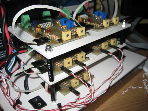
The hardware for elroy is almost complete, only the stretch sensors for the head to make and mount. I can now control the elbow, shoulder and head joints manually from the pc. Ive added a new video to show the operation of all joints. Ive also added a picture of the 5 motor control boards used to control the 10 motors.
Ive also been working on a computer model of Elroys arm, which im hopefully going to use to generate the information necessary for Elroys real arm to move to a given position.
Update - 10/6/10
I've made a new video showing the latest progress on Elroy. He has a new design head with a webcam and lcd display mounted in the head to give him eyes and a mouth! I have redesigned the motor control circuit with signal conditioning for the stretch sensors, and built and tested one of them, 4 more to make! Check out the video for more info!!
Update - 8/5/10
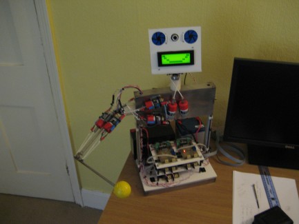
Elroy has a head!!! I have fabricated a new base for Elroy which the motors for the shoulder and the head are mounted to. I have also built another ball and socket joint for the head to be mounted to. The head at the moment is just a metal hoop but it will soon have a webcam mounted on to it, possibly driven by servos to allow the 'eye' to move. I have also mounted the LCD to the base and I am now powering the motors with a 12V SLA battery.
I am currently designing the improved motor control board, of which ill need 5 to control the 10 motors. I have the current monitoring working with the help of a low pass filter, and have designed an amplifier circuit to amplify the signal from the stretch sensors. The I2C code is now working and allowing me to collect data from the stretch sensors and the motor currents and send to the pc and be displayed, I can also control motor speed from the pc.
Update - 16/3/10
I have finished fabrication of the shoulder joint. I found the original shoulder design had a few flaws so decided to build a ball and socket joint. This is complete and the motors to drive the shoulder are mounted, check out the video for more information.
I have also been working on the I2C comms for the two controller boards which is going well. The next step is to re-wire the motors on the elbow joint, along with the stretch sensor and see if i can get some data to and from the pc to control the joint.
Hi everybody,
Up until now i have only built mobile robots, a few of which are posted on this site. I started reading up on AI and wanted to try and explore some ideas myself. I decided that mobile robots did not provide the type of test platform i required and so decided to start work on a robot arm. I wanted to use the human body and brain as the starting point of my research and so decided to build a robot arm that mimics the actuation and sensing capabilities of the human arm. So i give you Project ELROY! This is going to be a long term project, and a tough challenge. Up to now i have constructed a robot arm with a shoulder joint and an elbow joint, the elbow being the only one that is driven at the moment. I am using dc motors to drive the arm, but using a technique i haven't seen used anywhere else on a robot arm, some one please correct me if im wrong!! I am using the motor to turn loops of string between the motor output shaft and the robot arm, the theory being that as the string is wound up the length of it gets shorter. So far this technique seems to be quite strong and fairly controllable, with the added function of the arm joint being able to 'limp' when the string is loose, a biologically lifelike characteristic that is uncommon in many other actuators. I am using a stretch sensor from Merlin robotics as a position sensor for the robot arm, here is a link to their website http://www.merlinrobotics.co.uk/merlinrobotics/merlin-stretch-sensor-p-72.html
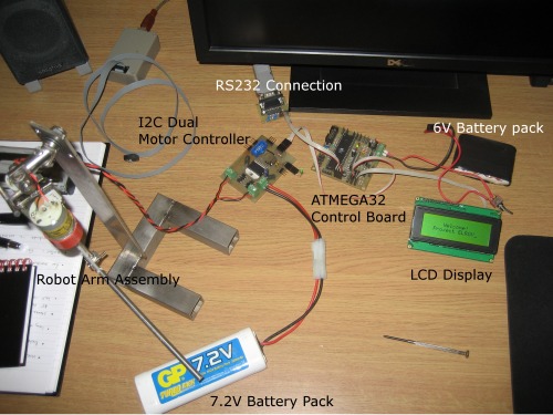
I have designed and built a dual motor driver, with an on-board ATMEGA8 to control the motors and read the stretch sensor. The motor current can be monitored aswell allowing the force that each motor is applying to the joint to be controlled. The motor control board will communicate via the I2C bus to an ATMEGA32 control board that will interface to the PC. I intend to use 4 more motors to control the 3 degree of freedom shoulder joint, which means another 2 motor control boards. Ultimately i plan to build another 3 DOF joint to make a neck joint and give ELROY a head! Theres more info in the video so enjoy and id welcome any feedback!!
Robot Torso
- Actuators / output devices: Como drills 12-24v motors
- CPU: ATMEGA32, atMega8
- Power source: 6V, 12v SLA
- Programming language: C++, C
- Sensors / input devices: Stretch sensor, Current monitoring
- Target environment: indoor