


Position aware robot
Update 14 November (2)
This is a screenshot from the plotted path with the adjustments:
Notice that I have followed a similar path as the path plotted in my previous version:
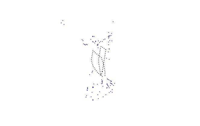
Notice that this time the lines are much closer to each other which makes sense as I went forwards, took a +/- 90 degree turn, moved forward again, 90 degree turn and went back to my origin.
It is much more precise than in the beginning.
This is due to 2 things:
1) Switched from magnetic compass to gyroscope
2) Usage of statistics to remove errors and noise from the gyroscope reading.
Yesterday I finished implementing a basic version of the gyroscope readings. The readings were much more precise than when using the magnetic compass or other way but there were still lots of erros due to noise.
I now filter out error readings and noise by calculating the standard deviation and only use those readings that are within the 3*standard deviation boundaries.
This of course is not 100% accurate but I am getting close.
I will improve the error and noise filter algoritm later on when I add the info from the accelerometer.
Update 14 November
After some additional research and forum questions I decided to do more research and study a little bit.
I bought a book about autonomous robots which provide all the information about sensors as well as the maths and algoritmes to filter the data, use aliassing and so on.
I also bought a book about probabilistic robotics which goes even deeper in the maths.
I'm reading a lot about these topics at the moment and will implement the stuff I learn into this robot to make it smart.
Currently I made some changes to the robot in order to optimize the accuracy of the path plotting.
I have removed the magnetic compass as it was only confusing me. It only really worked when going in a straight line in order to figure out the deviation from the straight line. Even then I got issues when the magnetic field got distorted inside.
So I removed the module and replaced it with a 6DOF IMU which contains a gyroscope and accelerometer. Currently I already implemented the gyroscope to calculate the rotation from the data from the gyroscope.
This works both for turning left/right as well as getting the deviation from moving forward and backwards. The plotting is much more accurate than before. Sometimes there is still a glitch where the calculated angle is way out but that's probably caused by noise in the sensor.
So far the implementation looks like this:
/**

This method is called every 10ms using the TimedAction library

Although we want to sample at 100Hz. We cannot guarentee the 100Hz as other stuff i nthe program might interfer

Therefore we need to calculate the duration for certain actions like turning and moving forward

duration calculated is in seconds as all the values from our sensors is in seconds (m/s for acc, degress/s from gyro)

**/

void Robot::sample100Hz(){

	unsigned long time = millis();

	float duration = time - lastSampling;

	duration = duration / 1000;

	if (currentMovement != 'S'){

		gyroCheck(duration);

	}

	lastSampling = time;

}


void Robot::gyroCheck(float duration){

	int values[3] = { 0, 0, 0 };

	getGyroscopeReadings(values);

	float angle = (values[0] - xOffset) * duration / 2.96;

	totalAngle += angle;

}
The only thing I don't understand is the 2.96 factor. I found this by trial and error but noticed that the reading I got from the gyro is not really degree/seconds. I have to devide it by 2.96 to get there but I don't know why...
When I start moving I set the totalAngle to 0.
So far this give me rather accurate data on the total change in angle during the movement. Even when moving forward the data is rather accurate as I can clearly see in the plotted data that the robot is not following a correct straight line which I can also see with the naked eye so the representation on the plotted map is an accurate model.
Currently I don't filter the data from the gyro which means that if there are spikes I could get messy information. However the sample rate is about 100Hz so a spike shouldn't impact that much as it will be balanced by the other 99 samples.
The idea is to keep all those samples in an array and calculate the angle change once every 500ms so after 50 samples. I can then remove the extremes and replace them with the average value.
This is not perfect but this should improve the accuracy a little bit.
When I read better algoritms in my books I will most likely implement those.
Next on the agenda is implementing the accelerometer so I can get more accurate distance travelled data. I will then also combine the gyro and accelerometer using a kalman filter to get proper filtered data which should increae the accuracy a lot. But that's not for soon as I first need to read up on the math.
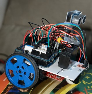
Introduction
For a beginner in robotics this seems like a big project. Some people had their concerns but I wanted to do something special. The robot is far from finished and I have some ideas for a 2.0 version but so far I am really happy with the result
Remote control
The ultimate goal is to let the robot move around on its own and tell him to go to a specific location and he should figure out how.
In order to build the software and do tests I first started to build the robot as an RC robot so I can easily test my software and sensor readings.
As RC method i have chosen for the XBEE wifi board and send all the command on the Serial. I then wrote an application that communicates with the XBEE.
You control the robot like a computer game. You use the WASD keys to move forward, left, backwards and right. You can also adjust the speed by using the shift key (speed up) and control (speed down).
Q and E are used for panning the ultrasonic sensor.
Because of this I can move the robot around myself while writing the software to plot its path and location. It's really easy to test everything using this platform.
Location, location, location
I had the idea to build a robot that can navigate on his own. Not just obstacle avoidance but a robot that knows where he is. If I put him in the room on some random location he should be able to figure out where he is by driving around a bit.
Because this process is really CPU intensive I came up with the idea of writing an application that runs on my laptop that can do the heavy calculations. The robot will send data to the application on a regular base. The application than plots out the data and will keep track of the robot its location.
Later on, I will use that data to calculate the location of the robot but first I need to plot the path of the robot which seems more challenging than I first though.
Ultrasonic + compass
The robot only has an ultrasonic sensor (ping) and a compass (CMPS10). Based upon those readings I needed to plot the path which is difficult!
I first came up with the idea of using the heading information in combination with the distance from the ultrasonic sensor. Looked straigh forward. If I'm moving forward I just take the differnce from 2 readings on the ultrasonic and I know the distance travelled.
This of course required the compass to work perfectly and the robot to move in a perfect straight line. As it appears none of those constraints are met. Apperently a building can mess up the reading of a compass due to the concrete and iron. The robot isn't moving exactly straight due to the lack of my building skills.
A lot of the time the relative heading chance is correct. So if the robot deviates a few degrees from a straight line, I can tell this from the heading reading.
In my calculatations I am using this info. The refresh rate of my info is about 600ms so if the angle deviates between -8 and +8 than I know it is because the robot is not moving in a straight line and I update the heading information. if the heading coming from the compass deviates more than 8 I believe this is because of magnetic field changes caused because of the building and I ignore those readings.
As for the distance travelled I took the circumference of the wheel and checked how long a single rotation takes. This way I calculated the speed of the robot. This gives me a rather accurate distance. If the voltage of my battery drops, the speed drops as well so I might add something to messure the voltage and take that into account in the calculations.
This is just moving forward and backwards. Moving left and right was a different challenge. I tested the heading coming from the compass and again there is quite some deviation because during spinning the location of the robot can change so the building can mess up the reading again.
I took the same principle as when moving forward. I calculated how many milliseconds it takes to turn 1 degree so I have a rather accurate idea of the angle. Because the servo's don't get the speed immidiatly I need to calculate a factor that is bigger when the angle is small but when the angle is bigger, the speeding up has a smaller effect on the total average.
Moving data
If the robot is moving it sends telemetry back to the laptop (using XBEE) over the serial. A typicall message looks like this:
M F 85 120 0 0 954
M is the identifier for a "Movement message".
F is the direction with F forward, B backwards, L left, R right and S stop
85 is the current heading reading from the compass
120 is the distance messured by the ultrasonic
0 is the pitch from the compass
0 is the roll from the compass
954 is the duration of the current movement.
In my application I use these messages to plot out the path of the robot.
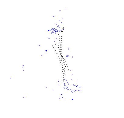
This is a screenshot taken after moving the robot around for a bit:
The black dots are location points and connected provide the path. The blue points indicate the messurements from the ultrasonic sensor so these are obstacle points. As you notice I went close the wall.
I moved around a few times and returned the bot to the its initial starting point and as you can see it's rather accurate. Not 100% but concidering the methods of getting the movement data, I am very happy with the results.
Next steps
So far I can control the robot using my laptop which works perfect.
The software also plots out the path taken by the robot. I have some ideas to increase the accuracy of the readings:
- Use Hall Effect sensors on the wheels to get more accurate readings for the distance travelled
- If the heading on 2 concecutive readings are correct, I might use both distance readings to calculate the distance travelled
Next on the plan is to persist the path taken and write an algoritm so I can make an estimation of the location.
I'm also looking to get some additional sensor to get some more info on the magnetic field.
As for the algoritm I was thinking on making a list of possible locations based upon previous readings. Every time the robot makes an additional reading I can increase the accuracy of the location.
If I install an additional sensor to get more info on the magnetic field it will be more easy to pinpoint the location.
There is still a lot of work but so far I am really happy with the progress.
Here's an additional screenshot from the application I wrote to control the robot and plot the path:
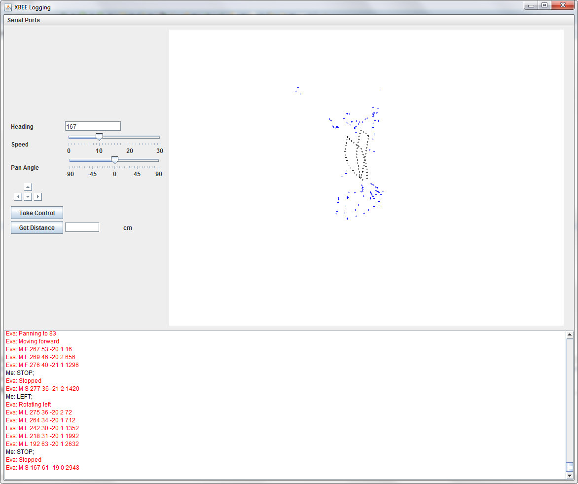
remote control, map path, knows position, avoid obstacles
- Actuators / output devices: 2x Continous Rotation servo's for wheels
- Control method: semi controlled using XBEE
- CPU: Arduino
- Operating system: Arduino C++
- Power source: 2x9V
- Programming language: C++, Java
- Sensors / input devices: Ping))) Ultra Sound, CMPS10
- Target environment: indoor