


Polypod - Taking a Stroll on the Cheap
Update August 16, 2011
The PCB boards arrived a day earlier than expected (ordered on a Friday, arrived the following Friday). Eleven brain boards and 66 leg boards. I'd buy fewer if I could but for $145 CAD from GoldPhoenix it's hard to find a better deal.
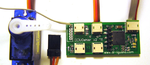
Here you can see a size comparison between a T-Pro SG90 servo, it's standard connector and the leg controller board. I decided to use 1.5mm (0.059") spacing connectors. The female connectors are insulation displacement (IDC) so I can avoid fiddling around with crimp pins. Although the IDC connectors are designed for a finer gauge of wire, the servo wires fit fine (as you can see in the photo - top middle connector).
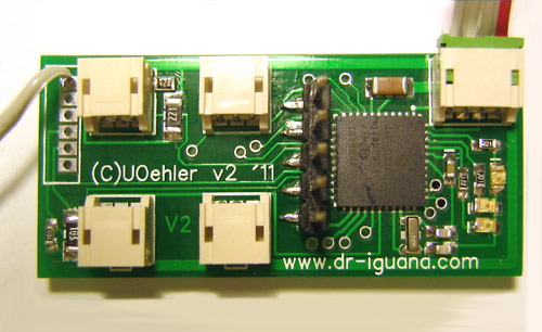
Sodlering the QFN was not as difficult as I'd feared, nor as easy as I'd hoped. Nonetheless, my AOYUE hot air station made the job fairly straightforward. Using a loupe you can see the solder connections in the small half millimeter or so gap between the QFN and the board. In a few cases where the joint was suspect, I used flux and my soldering iron tip on the pad that extends beyond the chip to wick solder underneath. Seems OK.
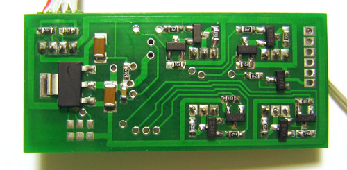
On the rear of the board you can see the NPN transistors that I use to level shift to 3.3V control pulse to the 6V for the servo. There are also 4 N-Channel MOSFETs that I hope to use to turn servos on and off. To the left you can see the 3.3V regulator that provides power for the dsPIC. The three sets of pads at the lower left are for setting the leg controller I2C address. With no bridges this would read as 0b111.
I'm off for a short vacation and then I'll be adapting the existing code to the new board. With luck the transition will be smooth. Afterwards I plan to switch the pulse generation code from using interrupts to using the hardware PWM capabilities of the dsPIC.
Update August 10, 2011
Oops numbers 3 and 4.
3) I ended up ordering some dust again. I wasn't paying enough attention and ordered 3.3pF caps in 0201. Turns out 0201 in metric is 0603 which is what I though I was ordering but not in metric.
4) I also erred in the dsPIC order. I ordered dsPIC33FJ128MC804 instead of dsPIC33FJ128GP804. Although the pins are almost identical the MC component is missing 4 analog ports and the PWM is quite different due to it being aimed at motor control. I'll have to order more dsPICS.
Sigh, nothing a little money can't fix. It's lucky that digikey delivers overnight in my neck of the woods. My boards should arrive from China on Friday. Getting excited.
Update August 7, 2011
Isn't it always the way that you spot problems after it's too late. So far I've spotted one Ohhh and one Oops but nothing fatal so far.
1) I designed the brain board around a micro USB connector. I'd never heard of micro USB before and confused this in my mind with mini USB. When the part arrived from digi-key I realized my error. Not a problem though. I'll just have to buy a micro USB cable.
2) The second error is more embarrassing. I forgot to route the micro SD chipselect line and I routed two small components on the wrong side of the board (i.e. under the SD connector). Duh! Not show stoppers though. The one component is a bypass cap and frankly there ought to be enough of these elsewhere so I'll ommit this one. The second is a pull-up resistor on the /CS line. Since I neglected to route the /CS line I can omit the resistor as well, I'll just drill a small hole by the resistor pad and connect it to ground with a small jumper to enable the SD card.
Hopefully nothing else shows up.
Update August 5, 2011
Time is a limited resource but I've been soldiering along. Since my last update I've been preparing the final board layouts for the leg controller and brain. I just sent the gerbers off to GoldPhoenix in China to fab the PCBs.
The leg controller boards are 0.8" x 1.8" and feature a DSPIC33FJ64MC804. The dsPIC is a QFN part so we'll see how successful I am in soldering. I have an AOYUE hotair station so it should be OK. My original design supported 3 servos. I added a fourth for future projects. My first code used interrupts to time the servo control pulses but in the next iteration I think I will use the built in PWM hardware. It supports a one shot mode that should be perfect. This chip supports 4 independent PWM channels hence 4 servos. The leg controller will normally operate as an I2C slave. Optionally you can add two pullups to the leg controller and use it as an I2C master. This way you could gang a few leg controllers together via I2C, change the software and maybe do some animatronics. Something for the future.
The Brain board (2.5" x 1.9") is more ambitious and time will tell whether everything works.
main processor is a dsPIC33FJ128GP804
PIC18F2553 (via serial) for USB support
MRF24J40MA (via SPI) for wireless communication
MicroSD slot (via SPI)
LM4880 stereo audio amplifier (power by the dsPIC's dual upsampling audio DACs) for sound
MMA7361L three axis analog accelerometer (for future biped projects)
L3G4200D three axis I2C gyroscope (for future biped projects)
10 connectors for I2C slaves
Single or Dual 6V buck regulators (power leg boards and servos from 3 series LiION batteries)
OK, that's all for now. This project has been a lot of fun so far. Routing the boards was challenging but very satisfying when done. I may kick myself for switching to TQFN, QFN and 0603 parts but I've caught the miniaturization bug. Smaller, smaller, smaller!
I've heard that rather than using expensive jeweler's loupes or dental loupes to do this fine work you can substitute reading glasses in the +3.5 diopter range. Anyone have experience with this? They're pretty cheap compared to $100 head mount loupes.
Update July 5, 2011
I've been converting the VB6 code into C for the last few weeks. I'm using Q16 fixed point instead of floating point. I've mounted a leg onto a stand so that I can test things. I've including a short video that shows the leg going through a gate cycle. The I2C communication between the brain board and the leg board works really well.
Next I'll be working on the proper brain board. The substitute I've been using is a bit light on program space. I'm hoping that before long I can send these off to China to make some proper PCB's and I'll finally be able to have more than one leg. :-)
The cheap servos are looking OK but some are a bit twitchy. These servos put a lot of noise onto the 5V power supply. Some 10uF capacitors soldered across the power leads to each servo helped alot but I may have to add more filtering. Hard to say whether these servos will be a problem but I'm optimistic.
--- Original Post ---
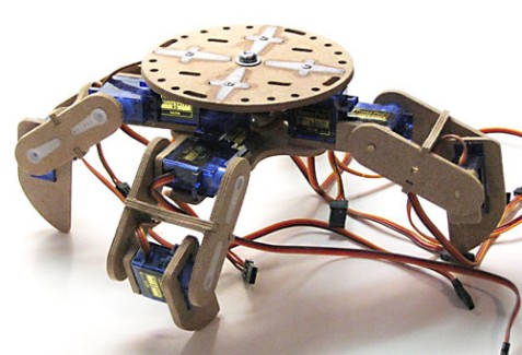
My goal is to build a richly featured walking robot but keeping it simple and cheap. I'm designing everything from the ground up. No using other people's code or PCBs. I'm hoping that by starting from scratch I can maybe contribute some new ideas. There are some really brilliant walking robots out there and I don't simply want to copy someone elses design.
At the moment, the project consists of three threads that are converging. The first is the mechanical design. This involves finding simple and cheap methods of building the required legs and body. 1/8" MDF is light, rigid and easy to work with. The entire body has been built from this.
The next thread is software. I started by simulating the robot in VB6. This allows me to perfect the inverse kinematics routines and methods for generating gaits. I've avoided looking at how others have done this in the hopes that I might come up with some new ideas or approaches. The video I've posted shows simulated quadrupeds and hexapods walking about. I'm nearly done writing the dsPIC33 code for the leg controllers. Shortly I should have a real leg on the test stand twitching and moving around. After that I'll program the brain board.
The final thread is electronics. I like to design and build my own boards. Each leg will receive a 40MIPS dsPIC33 to do the inverse kinematics and motion while in the air. It will also sense a couple of tactile switches and an optical sensor. The code uses signed 15.16 fixed point for speed. This board exists as a prototype. I'll probably do one additional revision incorporating what I learn.
The brain board hasn't been designed yet but I have another board I made that has substantially the same capabilities and it will substitute for the time being. It has a 40MIPS dsPIC33 plus a PIC18F2553 for USB support.
There's a developer diary over at my web site if anyone's interested in following along or reading about things in more detail. I'll update this post as I reach significant milestones. Once the project is done I'll share the entire design.
Cheers and happy building.
Yet another walking robot but starting from scratch.
- Actuators / output devices: T-Pro SG90 servo motors
- Control method: autonomous, USB during setup and testing
- CPU: dsPIC33 x 5 plus a PIC18F2553
- Operating system: none
- Power source: Li Ion 3 x 2400mAH
- Programming language: Microchip C30 C compiler
- Sensors / input devices: Sharp IR, Tactile, Optical
- Target environment: indoor