


PolarGraph
Getting there
Correct way up, got rid of skewing, and bends on straight lines. So close, except now its loosing track of its own positions. (so the brain isnt central in the jar) and its moving a bit jerkily, resulting in spots at each GCode point....
GCode
I decided to strip it back to basics, and write a sketch whereby i can upload a GCode file to an SD card, after a LOT of faffing around almost at ever last step, it now works...
- First i use inkscape to generate a path from an image, using a "generate G Code" function.
Then, the arduino:
- Reads the GCode off the SD card, a line at a time
- Parses out the X, Y and Z co ordinates (if there are none, it discards the line)
- moves the Gondala to the new co ordinates in turn, and raises the pen as required.
And here is this evenings final product. I si spent a long while getting the Accelstepper motors working, a long while getting the SD card to read a line at a time, and a long while getting it to parse out the coords. In the end, the conversion from cartesian to Polargraphic coordinates turned out to be really simple! Doh!
The image is a bit wobbly, i need to tinker with the speed and acceleration of the motors on a move by move basis, to remove the curves and steps. Still, its not a bad first go?
//LIBRARIES
#include <SD.h>
#include <AFMotor.h>
#include <AccelStepper.h> // Accel stepper used to allow for Curves and angled lines
#include <Servo.h>

//CONNECTIONS
File myFile; // instance of a file
const int chipSelect = 15; // adafruit SD breakout, wired 15 - 18. must use modified SD library to allow for reassignment of pins.
AF_Stepper StepperL(200, 1);  // Left Motor, M1 & M2
AF_Stepper StepperR(200, 2);  // Right Motor, M3 & M4 // Forward is Up on both motors.
Servo Pen;

void forwardstepL() {
  StepperL.onestep(FORWARD, SINGLE);
}
void backwardstepL() {
  StepperL.onestep(BACKWARD, SINGLE);
}
// wrappers for the second motor!
void forwardstepR() {
  StepperR.onestep(FORWARD, SINGLE);
}
void backwardstepR() {
  StepperR.onestep(BACKWARD, SINGLE);
}

// Motor shield has two motor ports, now we'll wrap them in an AccelStepper object
AccelStepper stepperL(forwardstepL, backwardstepL);
AccelStepper stepperR(forwardstepR, backwardstepR);


const int button = 13; //button holds the sketch in setup, until pressed. This stops the motors from moving under USB power while uploading.
const int led = 14;
const int relay = 2;

// DIMENSIONS
int offset = 1300; // offset along X & Y axis, to 0,0 centre position, from pivots
int scale = 5; // scale the image?

// WORKING VALUES
char inputCharString [100];
char inputChar;
int stringIndex = 0; // String stringIndexing int;
String stringX;
String stringY;
String stringZ;

double readX;
double readY;
double hL;
double hR;


boolean prevPenPos; // previous pen position, for comparison.

boolean penDown = false;

void setup()
{
  // Open serial communications and wait for port to open:
  Serial.begin(9600);
  // setup
  pinMode (led, OUTPUT);
  pinMode (button, INPUT);
  pinMode (relay, OUTPUT);
  Pen.attach(9);
  Pen.write(0);
  stepperR.setMaxSpeed(3000);
  stepperL.setMaxSpeed(3000);
  stepperR.setAcceleration(300.0);
  stepperL.setAcceleration(300.0);


  stepperL.setCurrentPosition(sqrt((sq(offset + readX))+(sq(-offset+readY))));
  stepperR.setCurrentPosition(sqrt((sq(-offset + readX))+(sq(-offset+readY))));


  Serial.print("Motors ready, Initializing SD card...");
  // make sure that the default chip select pin is set to
  // output, even if you don't use it:
  pinMode(SS, OUTPUT);
  // see if the card is present and can be initialized:
  if (!SD.begin(15,16,17,18)) {
    Serial.println("Card failed, or not present");
    // don't do anything more:
    while (1) ;
  }
  Serial.println("card initialized.");
  //Open file to read
  myFile = SD.open("J.txt");
  if (! myFile) {
    Serial.println("error opening datalog.txt");
    // If failed to open Wait forever
    while (1) ;
  }
  digitalWrite (led, HIGH);
  Serial.println("Waiting...");
  //hold
  while (digitalRead (button) == HIGH){   // stops script. Its waiting for a button press (LOW on "button")
  }
  digitalWrite (relay, HIGH);

  Serial.println("....Running");
}
void loop()
{
  while (myFile.available()) {
    inputChar = myFile.read(); // Gets one byte from serial buffer

    if (inputChar != 10) // Write to string until "end of line" ascii recieved
    {
      inputCharString[stringIndex] = inputChar; // Store it
      stringIndex++; // Increment where to write next
    }
    else
    {
      { // in this bracket pair, 2dp cooridnates extracted from Gcode.
        inputCharString[stringIndex] = 0; // Add last char as ascii "void" to stop from reading the rest of the string (from prev lines longer than current one)
        String inputString = inputCharString;

        if (inputString[0] == 'G') // if line starts with a G process it, if not discard it
        {
          int Xpos = inputString.indexOf('X'); //locate the position of X in the string
          int Ypos = inputString.indexOf('Y'); //locate the position of Y in the string
          int Zpos = inputString.indexOf('Z'); //locate the position of Z in the string

          if (Xpos > 0) {
            stringX = inputString.substring(Xpos+1,Ypos-1) ; // value for X is located between X and Y. If it exists, cut it into a substring
          } // if it doesnt exist it will remain as previous
          if (Ypos > 0) {
            stringY = inputString.substring(Ypos+1,Zpos-1) ; // value for Y is located between Y and Z. If it exists, cut it into a substring
          } // if it doesnt exist it will remain as previous
          if (Zpos > 0) {
            stringZ = inputString.substring(Zpos,Zpos+10) ; // value for Z is located after the Z. no more than 10 chars needed. If it exists, cut it into a substring
          } // if it doesnt exist it will remain as previous

          // TRANSFER Z STRING INTO BOOLEAN PEN POSITION
          if (stringZ.charAt(1) == '1') { // Pen up pen down, Z1.000000 is pen in up position
            penDown = false;
          }
          else    if (stringZ.charAt(1) == '-') { // Z-0.125000 pen is in down position
            penDown = true;
          }
        }
        if (penDown != prevPenPos) {// compare pen pos with previous. if different from prev update
          if (penDown == true){
            Pen.write(50);
            delay (1000);
          }
          else if (penDown == false){
            Pen.write(0);
            delay (1000);
          }
        }
        // TRANSFER X STRING INTO FLOAT (2dec place)
        char carrayX[stringX.length() + 1]; //determine size of the array
        stringX.toCharArray(carrayX, sizeof(carrayX)); //put readStringinto an array
        double  readX = atof(carrayX); //convert the array into an Integer
        // TRANSFER Y STRING INTO FLOAT (2dec place)
        char carrayY[stringY.length() + 1]; //determine size of the array
        stringY.toCharArray(carrayY, sizeof(carrayY)); //put readStringinto an array
        double readY = atof(carrayY); //convert the array into an Integer

        Serial.print("X: ");
        Serial.print(readX);
        Serial.print(" Y: ");
        Serial.print(readY);
        Serial.print(" penDown Boolean: ");
        Serial.println(penDown);

        readX = readX * scale;
        readY = readY * scale;
        double hL = sqrt((sq(offset + readX))+(sq(-offset+readY)));
        double hR = sqrt((sq(-offset + readX))+(sq(-offset+readY)));

        Serial.print(" hL: ");
        Serial.print(hL);
        Serial.print(" hR: ");
        Serial.println(hR);

        stepperR.moveTo(hR);
        stepperL.moveTo(hL);
        while (stepperR.distanceToGo() != 0 || stepperL.distanceToGo() != 0) {
          stepperR.run();
          stepperL.run();
        }
      }
      prevPenPos = penDown; // update prev Pen Pos
      stringIndex = 0; // clear the String index value for the next cycle
    }
  }
  myFile.close();
}
Overview
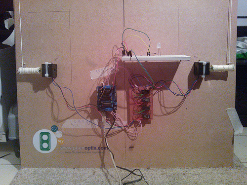
So following the request in the comments, here is a brief overview of the device to date!
As you can see i have moved it all onto a mounting board (bit of wood i found). the board on which the paper is mounted can be any size i desire! limited only by the length of the lengths of string!
So, running from Top left to bottom right
- Stepper Motor: A small motor, with many steps, 200 per rev i think, a NEMA 15 size? The spool is a sewing bobbin, pushed onto the end. It is a very snug fit so no glue required! I have put two brass eyelets into the wood as string guides. Not nessecary really. There are two, because i toyed with having counterweights, but they really were not nessecary, so i took them off.
- Arduino Uno, with an Adafruit motor board on top. I have also soldered header pins onto the AVAILABLE pins only. this way i know which pins i can and cannot use, and dot have to keep looking them up. any pin with no header is in use by the motorshield! free pins are 2, 13, and all the analogue pins. I have also added header pins to the 5V power take offs. The adafruit motorshield also has two dedicted servo connections. i used one of these for my "pen lift" function while that was in operation.
- Relays. i found that pulling on the strings during setup span the motors, which in turn created voltage, which was sufficient to light up the power LEDs on the motorshield and arduino. I suspect this isnt healthy! so i built a relay into each coil of the two motors. The relays are activated (closed) by taking a single pin high. While the pin is low you can spin the motors to your hearts content and there is no physical connection between the coils and the boards. My sketch is set up so that the pin is only pulled high when required! i could just put the pin onto a 5v line to have the relays closed whenever the unit has power.
- Breadboard! A simple piece of bread board. this paticular one is very old! used as expected. in this photo i have a simple push button which is set up as a "begin" button. Also an LED to indicate "ready" and "finished". In my colour drawings i used an RGB LED to tell me which pen was required next! Next is to add an SD card breakout to allow me to use an SD card for data
- Lastly, the other stepper motor!
In short, the machine connects to a PC via the USB. i currently use two sketches. One on the PC, written in "Processing". This sketch scans across a Jpeg image, one line at a time, and returns a stream of serial (ascii) values. either 1-9 based on the value of the shade, or colour density at that point of the image, or a CR or LF command, which basically say "you have reached the end of the picture, turn around and go back"
A second sketch on the arduino, takes this data and uses it in a variety of ways depending on what the picture drawing technique it. it does one step at a time, and responds with a hand shake. (ie: get and instruction > do it > respond "done it")
and thats about it! ive done it as a learning exercise, so i havent done it in the most efficient way, or the most flexible way, the machine is dumb, and both sketches must match each other perfectly to get the correct result, but ive learnt alot. As a "learn about robots, and arduino" its a really good base platform. Easy and cheap to setup, with lots of room for development
If you want to see it done properly, by someone who know how to code properly (and who inspired my build)! check this out:
http://www.polargraph.co.uk/
More Arts
Nothing has changed regarding the robotic side of it, but i wore out my cheapo black pen. My girlfriend gave me a slightly battered 0.2mm thick expensive drafting pen. I ran the drawing below at a nice high res, nice and slow so there were no jitter on heavy high quality paper. If i say so myself, it looks immense in real life :) very pleasing to look at. I might get my proper camera on it some time.
Did i mention i did pen lift?
I dort think i did. It was earlier this year, and subsequently i have reached the end of my current abilities. I think its time for a full strip down of the code, and try and make something that can handle vectors. though that will require going back to grass roots. My current protocalls are just not set up in that way! anyhoo. penlift!
28/03/2013 - Video
12/03/2013 - Colour!
Basically, the rgb LED at the bottom, requests the colour of pen required, and the sketch goes over the image 4 times, with a button press required between each to allow for a pen change. On each pass it looks at a different colour. I had no end of problems trying to work out how to translate rgb, from processing, into cmyk, for printing (look up subtractive and addative colour some time). In the end it turned out to be really simple! I then spent a good 3 hours trying to get a number of "if" loops to work, to choose the colour being focused on for each loop. In the end i had a brain wave, sacked it in and decided to populate an array with the SAME data on each pass, but each pass takes a different value out of the array. (C,M,Y and K, in one "int")
Anyway, the Picture isnt PERFECT, but thats not the point of the polar graph. Despite needing a heavier amount of blue Im really happy with the outcome, especially for some cheapo £1 fine liners from the supermarket (Baby blue, Pink and yellow are close enough right?)
It is also plotting in both directions, rather than carrige returning, and i bought some "nice" paper and a board portfolio to keep copies of my best pictures in. I will get my webcam setup for a timelapse video, and run over the LMR logo again for you!
07/03/2013 - To do list:
Increased the row resolution to 50 rows. Getting there! I now have a few options for what to do next. some important, some pointless!
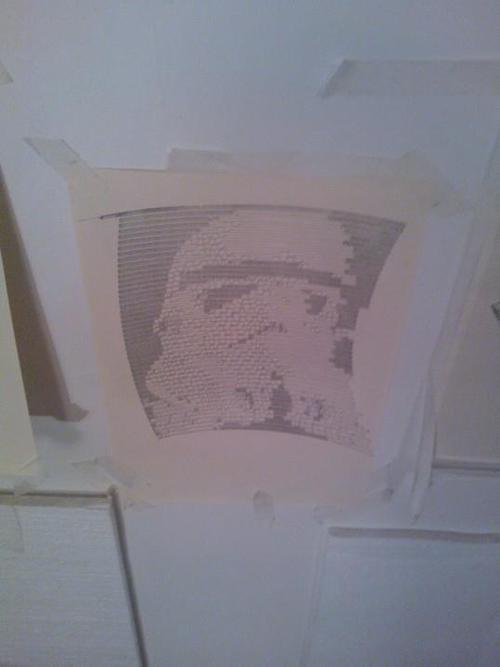
- I think the irregularities on the RHS are possibly due to the “white” reference resulting in 9 steps (due to being a transmitted byte of 9) 9 should be over ridden to be 1 step only. that should sort that. SORTED!
- Currently plots left to right, returning at the end of each line. this results in a single line in between each row, and an addition of 2 steps between each row (so the stormtrooper ends up with a long face). It would be much tidier to plot left to right, drop to the next row, and plot right to left. should be able to work that out i reckon….
- The image is getting pretty skewed! options to reduce this: 1)Make the image smaller, 2) move the motors further away, or 3) start worrying about compensating for the effect in the code. I prefer options 1 or 2, my maths wont stand up to that degree of scrutiny.
- The Arduino code needs to be updated each time, so that it knows the image resolution required! No reason why the processing code cant populate these pieces of information in the “setup” loop, so uploading a new image is all that needs to be done!
- RGB. The processing (PC end) code currently reads the “D” off an HSD image (HSD stands for, Hue, Saturation, Darkness, and was a simple way of pulling out greyscale data). If it processed as an RGB image, it could be made to sketch a Red image, return to origin, then light the RGB with a “pen colour request”. The user (me) would then insert the required pen, and it will then run over the next colour, as required. With an RGB led, there would be no reason why it couldn’t be a CMYK colour set either. (The next step on from this would be to make a system of swapping the pen automagiaclly)
- Add hardware! steppers are getting pretty warm. Im certain they are fine, so its a bit pointless, but i COULD add some temperature sensors to them and feed the info back to the PC for a “pointless readout”….
06/03/2013 - Serial success
thanks to Antonio, Chris the Carpenter and many others:
i need to fiddle with the constrains of black and white, to increase the contrast, but thats a job for tommorow. bed time now.
31/01/2013 - 2D arrays
a simple image with a 2D array. still drawing the image at 45 degrees.
http://pastebin.com/UZHfUAbN
need to work out a way of flipping an image through 45 degrees, while maintaining the pixel direction.
I think i need to establish whether a 2D array can have Rows of different lengths, and if so, how do i count the number of integers in a row?
that, or try and average the inbetween cells, but i think that would cause undesired fuzz on an image that is already very low res....
25/01/2013 - Hit a stop!
I think ive hit a stop. My approach is somewhat sloooowwwww. It involves drawing a picture, upside down no less, in excell, using conditional formatting to show the shades. ie: depending on the number typed, the cell changes shade. Then exporting the file, as a csv, gives an array of figures, which can be dropped into an array within the sketch. the sketch then references these numbers as "cases". each number, 1 to 8, has a different response. The final image looks just fine, but it is a hell of a clunky way of doing things, and i have now found that arrays have a maximum size (or so it seems)
here is the code as it stands: http://pastebin.com/wrjCVEVs
I think its time for a full rework, from a totally different approach. annoyingly, i have NO idea how to use serial to push data from a computer, nor how to process images into some kind of useful format. maybe i should learn some inkscape, and see what data i can get it to output, and THEN devise a sketch which can process this data....
24/01/2013: can you tell what it is yet?
my first attempt at a drawing. I "drew" it in MS Excel, and then exported the numbers as CSVs so it is a bit shonky. the theory is there, i think i will both strip back the code and try and refine it, and increase the resolution at the same time.
Update 2: 23/03/2013
i noticed that pulling the gondola by hand, spinning the servos, caused the arduino to light up, even if not plugged in. This CANNOT be good. I may have sorted this in a daft way, and certainly not the cheapes (relays are 2 quid each in maplins, the scumbags) but its sorted:
the breadboard holds a bank of DPST relays, one relay for each coil of the steppers, 4 relays. The signals from the motorshield are passed through the relays, before onto the motors. The "coils" for all the servos, take 5v and ground off two common rails, which are powered by the 5V source on the arduino. This way, unless the arduino has power (ie, is running, the gates are open, preventing current passing back into the motorshield and arduino. i have left the 5v and ground rails as header pins, so they could be sent via the breadboard, to allow for software switching on the arduino.
clear as mud?
the rest of the connections are soldered, as i dont have any screw terminals lying around, so the motor shield and relay array are now connected, which makes it a little awkward to handle. hopefully i shouldnt need to handle either of them much! one day, i may tidy it up, and perhaps make the relay pcb into a shield which stacks on top of the motorshield... that would however require parts which i currently dont have, and i am impatient.
you probaly cant see from the pictures, but all the circuitry, is hooked, through the mounting holes, onto little brass hooks from B&Q. seems to work pretty well! the breadboard i hooked onto some similar 90 degree hooks, and due to the holes in the breadboard being quite deep, it holds it horizontal nicely.
Update 1: 21/03/2013
So i found my lego gondola was dragging on the paper, and therefore was causing the pen to wiggle. only slightly but too much. so i now have a new plywood and plastic superlight, super slippy, super regular gondola.
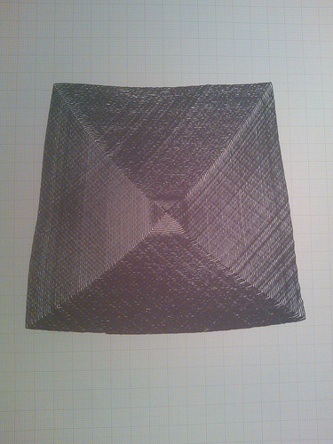
I also played with a few sketches. First i did a diamond, which grew in ever increasing increments of two. steps. Easy peasy, as only one motors runs at any one time (the library is "blocking" so can only run one motor at a time. The image worked pretty well, and showed some nice "skewing" of the shape as it grew out of the centre of the plot area, you can just about make it out, here, but i let it run to full page size, and it really obvious on the extremes
Then i decided to run both steppers at the same time, allowing for horizontal lines, and vertical lines. This is achieved by using a "for" instruction, and stepping each motor in turn, 1 at a time, until it reaches the desired position. The machine is currently, (whirring away on my left as I type) running a Horizontal and veritcal square, again, to see how the image gets distorted as it gets further from the plot centre. I acccidentally made it do a square that gets 1 step bigger per verticies, so this is going to take ages! it looks awesome so far though! stay tuned.....
Tadaa.... Note the graph paper background, showing the distortian. also, the wiggles are quite cool, i think they are there because i am using "single steps" and could be eliminated by microstepping using PWM to make a much smoother line, much slower...
ORIGINAL TEXT 19/03/2013
I found a couple of polagraph/Vplotters on the interwebs, and loved the images they had produced. Seemed like a really good arduino project to play with.
The physical side of it is really simple to get working, and only slightly complicated to get working well. I think it is a good testbed for projects, as the real key is in the algorithms used. It hads taken me only a few hours to build the unit, and get it to produce some simple but pretty abstract images.
The real work now starts. I could use a pre built program, to use the setup as an effective plotter, but i would much rather end up with less impressive pictures I have done myself!
Here is the electronic setup:
An Arduino Uno and an Adafruit motorshield on the left. The motorshield has unused pins broken out into headers, so that i can connect them to inputs/sensors on the breadboard (middle, obviously) Currently it just has a "begin" button, as while uploading a sketch, the unit starts on the existing sketch due to being powered up. The basic sketch hangs in the "setup" until the button is pressed.
And on the right one of the two Nema14 stepper motors, with a bobbin of nylon cord. the cord goes up to an eyelet at the top of the board. Why not mount the motors at the top like most people you ask? Simple, I didnt have enough wire to extend the stepper feed wires, but did have lots of Nylon cord!
And here it is as a whole. For the gondala i needed light, but strong material, which was easy to form into reliably geometrical/symetrical shapes. Ideally, i wanted to experiment with a few gondala designs so it needed to be modular too.
Up into the loft to retrive my Lego! (i'm 27, and have spent most of today sitting in a pile of the stuff)
the current one is totally different to the one picture, but i will get a better res picture up soon.
and here is my first creation (other than stepper tests, as above)
Nice and Geometric, straight parallel lines, but i like how the pen has scuffed the paper in an organic way.
Now to play with the code. I think some kind of "fractal" patter could be interesting.....
Plots lines
- Actuators / output devices: 2 Stepper Motors
- Control method: Semi-autonomous
- CPU: Arduino
- Operating system: Ubuntu (Linux)
- Power source: 9V, 1.6A for both the processor and motors
- Programming language: Arduino C++
- Target environment: indoor