


PID Based Line Follower
Hello LMRians,
This is a PID implemented line follower using an Arduino ATmega168 clone, Pololu QTR-8RC sensor array, a Pololu TB6612FNG Motor Driver, and super fast and zippy pololu micrometal gear motors. ( 30:1 Gear Ratio, MP version)
PID? Is that the name of a super hero or a mega villain? It's kinda both. If you manage to tune the parameters perfecly, you'll be fascinated by the results that follow, however, at the same time, you're gonna have some sleepless nights if you get it completely wrong. :D
I am no expert here, but what information i have understood about PID, might be helpful for some beginners like me to take your next project up a notch. Basically, when implementing PID, your goal is to achieve a setpoint value. You do that by calculating your error, which is the difference of the setpoint value and your current value. For eg: in this line following robot, our setpoint value is the position of our bot when the middle sensors are exactly above the line it's following. Our current value is obviously the position of our robot at any instant. The error, as mentioned previously is the difference of these two values. Then, by multiplying the error with specific coinstants ( Kp, Ki, Kd), the motor speeds can be "predicted" as to smoothly follow a line.
I wrote a small tutorial on implementing PID in a line follower.
In other words, this robot follows a line not only by detecting the turns ( yep, that's the basic principle), but also by calculating the error, which is how far it has moved off the track, and then adjusts the motor speeds using the Proportional, Integral and Derivative technique, in short, PID.
There are many articles and infos across the web about PID, methods of fine-tuning the PID parameters, take a look, and see the results for yourself!!
THE BUILD:
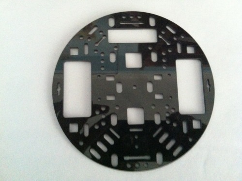
With no 3D printer or CNC machine lurking around my place, and also with an intent of taking part in a national competition, i had to resort to a pre-manufactured simple stable chasis, that could to the job. I used a Pololu circular acrylic plate for the robot body.
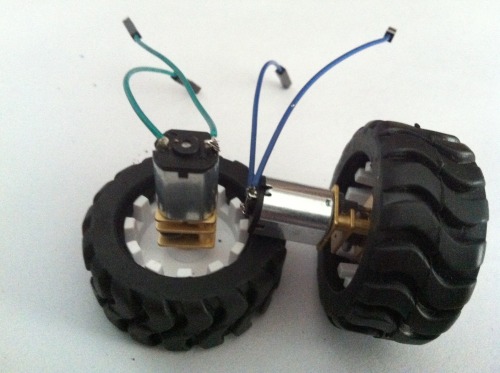
Next up, i needed some grippy wheels and some super fast motors to get the most out of my PID routine. Again, i ordered a pair of pololu's popular micrometal gear motors, along with a pair of extended brackets, and a grippy tire set. The motors are rated at 6.0 V and reach speeds of 730 RPM.
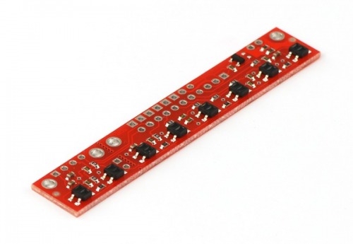
For the line tracking part, i used the Pololu QTR-8RC array. It not only detects whether the line is bright or dark, but it intelligently is capable to determine the line position. I am pretty much impressed by this sensor, and with the arduino libraries, it is a nice choice for building a speedy line follower.
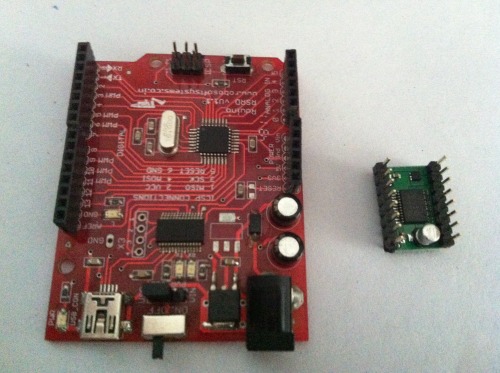
Then, i needed a powerful microcontroller to make the the error calculations fast as possible. Although not that powerful, i used a 16MHz ATmega168 Arduino clone, and it did not disappoint.
To handle turns and change directions in a snap, i needed a motor driver IC that was capable of effectively braking the motors when the PWM signal went low. For this i used the Pololu TB6612FNG Motor Driver. I wrote a little tutorial on controlling the direction and speed of two bi-directional DC motors using this motor driver here.
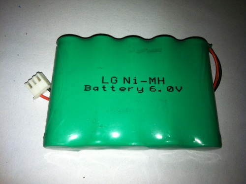
For powering up my system, i used a Duracell 9V to supply a stable 9V to my Arduino, and as a temporary choice, i used a 6.0 V Ni-MH battery pack, which i soon plan on replacing with a lightweight Li-Po battery.

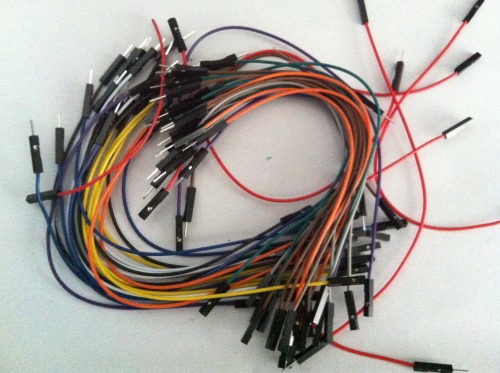
And then, i used some jumper wires for connecting respective pins across the robot.
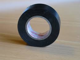
And finally some black electrical tape to make sure everything is in its place. Loose wires spell trouble!! Have been knocked out a couple of times from line following competitions, you don't want to repeat that mistake!! :D
Assembling the chasis is as easy as it gets. The sensors rest at a perfect height from the floor and the motors and wheels are a tight fit. I ordered the parts individually, but more or less, it is pretty much a line following kit. Of course, there are several other mounting options and expansion slots on the acrylic plate, you can hack it to make it something more than just a line follower.
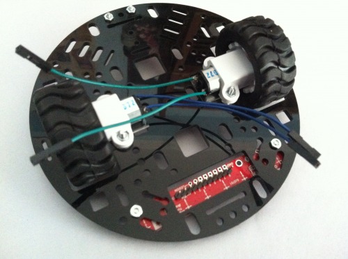
This is what it looks like with the sensors, motors, and wheels mounted on to the plate.
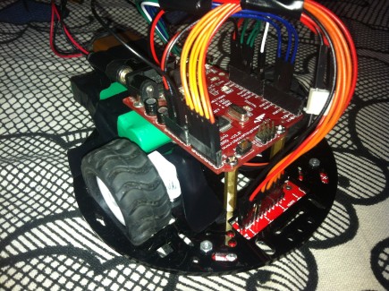
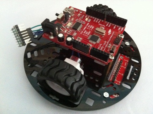
Then i simply mounted the motor driver and the Arduino. ( big deal!!!)
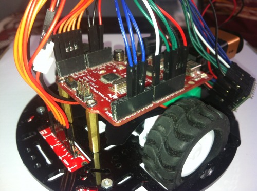
And finally added the battery pack at the back, made the connections accordingly. This is what it looked like at last.
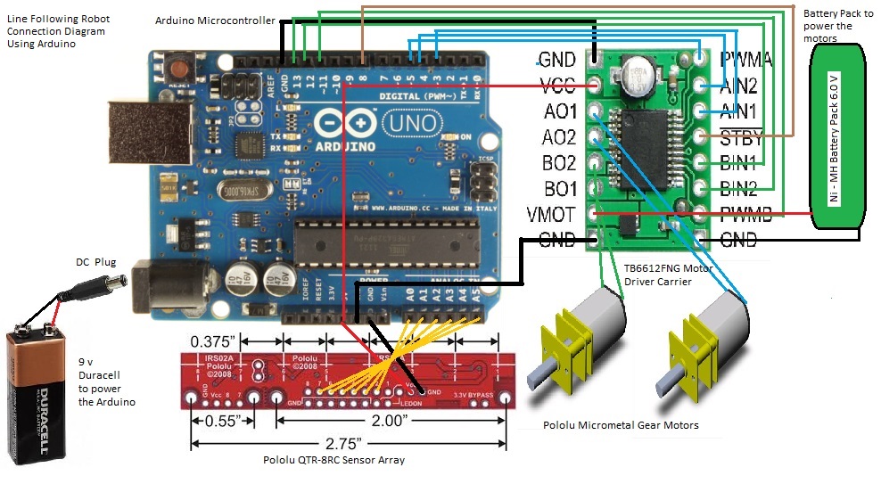
And here is a diagramatic representation of the connections to be made, if you're having some trouble connecting. Click on it for a better view.
And then, the reason why it's working, "DA CODE" !!! :D
PID Based Line Follower Arduino Code
UPDATE: 1/6/2014:
Thanks to Ladvien, one of the few LMR geniuses around here, I came to know about "Source Code Beautifier". I have removed the boring download link to the code and instead, have pasted the code right here, with some colours and added beauty!!
1 2 3 4 5 6 7 8 9 10 11 12 13 14 15 16 17 18 19 20 21 22 23 24 25 26 27 28 29 30 31 32 33 34 35 36 37 38 39 40 41 42 43 44 45 46 47 48 49 50 51 52 53 54 55 56 57 58 59 60 61 62 63 64 65 66 67 68 69 70 71 72 73 74 75 76 77 78 79 80 81 82 83 84 85 86 87 88 89 90 91 92 93 94 95 96 97 98 99 100 101 | #include <QTRSensors.h> #define Kp 0 // experiment to determine this, start by something small that just makes your bot follow the line at a slow speed #define Kd 0 // experiment to determine this, slowly increase the speeds and adjust this value. ( Note: Kp < Kd) #define rightMaxSpeed 200 // max speed of the robot #define leftMaxSpeed 200 // max speed of the robot #define rightBaseSpeed 150 // this is the speed at which the motors should spin when the robot is perfectly on the line #define leftBaseSpeed 150 // this is the speed at which the motors should spin when the robot is perfectly on the line #define NUM_SENSORS 6 // number of sensors used #define TIMEOUT 2500 // waits for 2500 us for sensor outputs to go low #define EMITTER_PIN 2 // emitter is controlled by digital pin 2 #define rightMotor1 3 #define rightMotor2 4 #define rightMotorPWM 5 #define leftMotor1 12 #define leftMotor2 13 #define leftMotorPWM 11 #define motorPower 8 QTRSensorsRC qtrrc((unsigned char[]) { 14, 15, 16, 17, 18, 19} ,NUM_SENSORS, TIMEOUT, EMITTER_PIN); // sensor connected through analog pins A0 - A5 i.e. digital pins 14-19 unsigned int sensorValues[NUM_SENSORS]; void setup() { pinMode(rightMotor1, OUTPUT); pinMode(rightMotor2, OUTPUT); pinMode(rightMotorPWM, OUTPUT); pinMode(leftMotor1, OUTPUT); pinMode(leftMotor2, OUTPUT); pinMode(leftMotorPWM, OUTPUT); pinMode(motorPower, OUTPUT); int i; for (int i = 0; i < 100; i++) // calibrate for sometime by sliding the sensors across the line, or you may use auto-calibration instead /* comment this part out for automatic calibration if ( i < 25 || i >= 75 ) // turn to the left and right to expose the sensors to the brightest and darkest readings that may be encountered turn_right(); else turn_left(); */ qtrrc.calibrate(); delay(20); wait(); delay(2000); // wait for 2s to position the bot before entering the main loop /* comment out for serial printing Serial.begin(9600); for (int i = 0; i < NUM_SENSORS; i++) { Serial.print(qtrrc.calibratedMinimumOn[i]); Serial.print(' '); } Serial.println(); for (int i = 0; i < NUM_SENSORS; i++) { Serial.print(qtrrc.calibratedMaximumOn[i]); Serial.print(' '); } Serial.println(); Serial.println(); */ } int lastError = 0; void loop() { unsigned int sensors[6]; int position = qtrrc.readLine(sensors); // get calibrated readings along with the line position, refer to the QTR Sensors Arduino Library for more details on line position. int error = position - 2500; int motorSpeed = Kp * error + Kd * (error - lastError); lastError = error; int rightMotorSpeed = rightBaseSpeed + motorSpeed; int leftMotorSpeed = leftBaseSpeed - motorSpeed; if (rightMotorSpeed > rightMaxSpeed ) rightMotorSpeed = rightMaxSpeed; // prevent the motor from going beyond max speed if (leftMotorSpeed > leftMaxSpeed ) leftMotorSpeed = leftMaxSpeed; // prevent the motor from going beyond max speed if (rightMotorSpeed < 0) rightMotorSpeed = 0; // keep the motor speed positive if (leftMotorSpeed < 0) leftMotorSpeed = 0; // keep the motor speed positive { digitalWrite(motorPower, HIGH); // move forward with appropriate speeds digitalWrite(rightMotor1, HIGH); digitalWrite(rightMotor2, LOW); analogWrite(rightMotorPWM, rightMotorSpeed); digitalWrite(motorPower, HIGH); digitalWrite(leftMotor1, HIGH); digitalWrite(leftMotor2, LOW); analogWrite(leftMotorPWM, leftMotorSpeed); } } void wait(){ digitalWrite(motorPower, LOW); } |
Feel free to roll over the code, and make appropriate changes as per your robot's specifications. An instant transmission to your microcontroller using the magic "copy paste" might not work ;-) . I hope you'll get a fair bit of an idea how line following works using PID. :-)
Although i have mentioned PID, i have just used the Kp and Kd constants in the code. ( So, it's pretty much a PD based line follower). When it comes to line following, it is not mandatory to include Ki in the equation, but you can try and see how it goes
You may notice, the Kp, and Kd values are set to 0 in the code. Now to find these constants it's up to you, what's the fun in not finding it? experiment, and gud luck. Note that the Kd value should be much more bigger than the Kp value.
I intend to upgrade this bot, and soon grow it on my own custom chasis, maybe further fine-tune the PID constants, and of course, increase the speed. Probably also make use of encoders, just to let the robot "foresee" the turns and let it know what the speeds at various points should be. I'll also study some more about PID, and hopefully post some more helpful info on it. Till then, that's all guys!! Thanks for reading :-)
Ashim
Chases down a line pretty fast
- Actuators / output devices: 2 x 30:1 Pololu micro metal motors
- CPU: ATmega168 16MHz Arduino Clone
- Power source: 6.0V Ni-MH for the motors, Duracell 9V for the Arduino
- Programming language: Wiring (Arduino)
- Sensors / input devices: Pololu QTR-8RC Sensor Array
- Target environment: On your kitchen floor or a chart paper with a line on it