


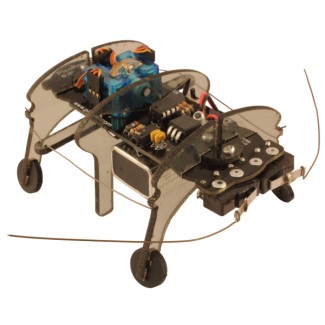
PicoRoach - 3 Servo Walking Robot
Now available from PicoKit!
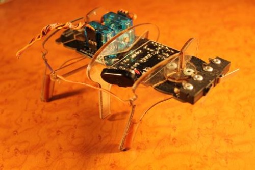
- A cheap and simple 3 servo robot walker that anyone can make for under $40. My students in Industrial Technology loved this project, as they could program it easily with PicoFlow Alpha. We used a PIC12F508 from Microchip Technology, and programmed it using the PicoFlow USB (in circuit) PIC Programmer. The plastic parts were cut from Polycarboante so they wouldn't break. Check out the development stages below.
Cost: under $40
Design Time: about 90 hours
Build Time: about 3 hours
Tools used:
- soldering iron
- screw driver
- pop-rivet gun
- sharp art knife or dremel
- pliers
- file
Early Development:
The first stage was to design the walking mechanism. I used autocad to record my developments. This first pic is of the inital mechanism idea, which changed substantially over time (although it always stayed a 3 legged robot).
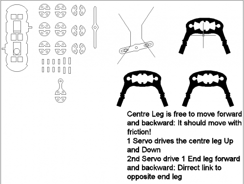
The main decisions encountered at this stage were the linkages and how much movement should occur. Should all three legs tip (alternately) and move back and forth? You can see, on the main pcb shape, two little pivot points jotting out, one on each side. These were possibly going to control alternate up and down motion, so the center leg would control the pivoting of the front and back legs. This design failed because it would not allow for the motion of the robot to turn on the spot.
The next picture shows the progression of the design, finalising angles of rotation, and progressing on the pcb layout.
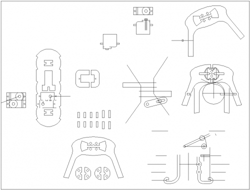
Here, I was toying with the idea of using a fixed linkage system between the legs to transfer movement from the back legs to the front. Although I ended up simply using some MIG wire which is very stiff and holds shape quite well. You can see from the pcb shape that I was still considering the center leg to move backward and forward, which wasn't going to work. I was also building into the design, the size constraints of the servo motors.
Prototype:
Stepping much further ahead, this picture shows the diptrace software I used to create the printed circuit board. I imported the outline of the pcb from a dxf file, because the measurements were quite important. Using the pcb as the main body of the hexapod was one of my best ideas, because it really cut down on the complexity of running the servo wires, and wires to the microswitches. Really, I can't actually remember not wanting to use the pcb as the body. It must have been one of my first thoughts.
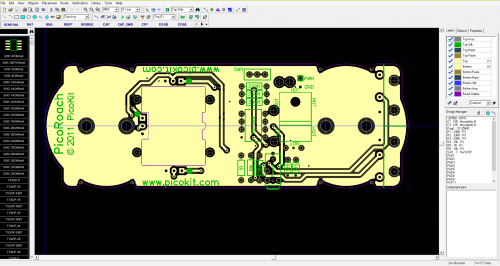
This design is actually my most recent, because I have plans to add a 9V battery bracket in there, with some rubber insulation. You can see the cut-outs for the servos aren't actually 'cut out', but the board manufacturer had no problems with this. I use PCB cart in china, and they have been really helpful at times, picking up on my little mistakes, even before they made the pcb. All credit to them. I only ever had one issue (about 6 years ago) where they drilled some holes .2mm undersized. Other than that, they have always checked their products for quality, and made new pcbs when they have stuffed up.
The prototype below was not my first. I actually hand make my circuit boards first. But this one shows the initial rubberbands for feet - lol. And since this prototype, I have actually flipped the pcb over so the battery hangs underneath to provide a lower center of gravity. The video doesn't show it, but on a smooth surface, the PicoRoach started backflipping because the weight of the 9V was too high.
You'll also not, the long servo wires and how ugly the microswitches are on top of the pcb. I also originally used breadboard jumper wires to connect the front and back legs. With the plastics, I tried acrylic, which had a much nicer finish, but the 0.8mm holes in the 3mm acrylic kept snapping if the wire linkages were bent over while in the holes. Changing to polycarb worked nicely, but I'm about to trial acrylic again, as another teacher has pointed out a good way to make a thicker walled hole. We're looking forward again to nice colours, and smooth edges.
Programming:
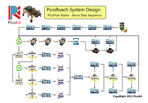
Programming the PIC MCU (Micro-Control Unit) was easy using the PicoFlow Alpha software. The three servo motors work by loading the with values from the Lookup Tool. The four Lookup Tools record the stepping sequences for Forward, Backward, Turn Left, and Turn Right movements. The Forward Lookup Tool is the standard motion, but when an antennae is triggered, the motion changes to 6 backward steps, and then on to 6 turning steps.
Future Development:
And with appearance, I've just milled out a mould that I designed in autodesk Inventor. It has a recess for the switch (which is now on top) and once vaccuum formed, the side recesses will be cut away to leave openings for the legs.
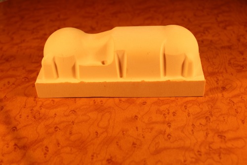
I can't wait to paint some eyes on the enclosure when it's made. Should look slick! I'll post another video when it's done.
Please ask any questions about the build, or contact me personally.
Cheers,
Phil
Navigates around by touched antenae
- Actuators / output devices: 3x Miniature Servo Motors
- CPU: PIC12F508 from Microchip Technology
- Operating system: PicoFlow Alpha
- Power source: 9v battery
- Programming language: C, ASM, Flow-Circuit
- Sensors / input devices: 2x Microswitches
- Target environment: outdoor