


PiBot-A
EN: PiBot-A will be present at German Raspberry Jam Pi and More on June 20 in Trier.
DE: Ich werde PiBot-A auf der Pi and More am 20. Juni in Trier vorstellen:
- Programm
- Vortrag für Einsteiger
- Vortrag für Fortgeschrittene
- in der Ausstellung: PiBot-A und PiBot-B
Short description:
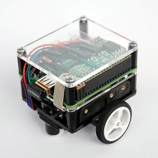
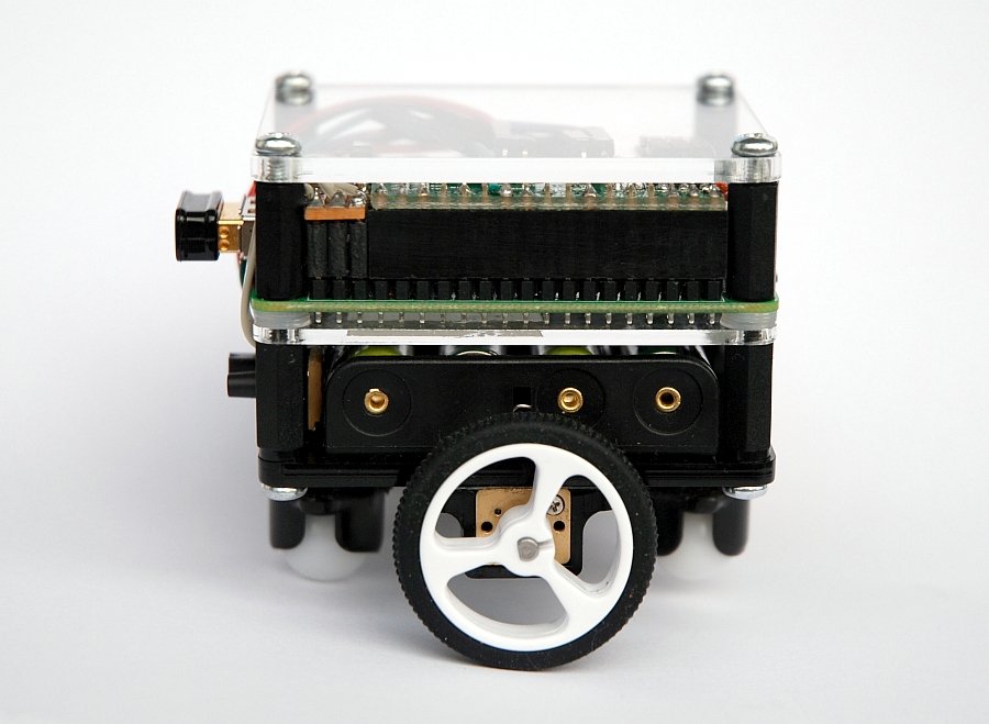
PiBot-A is a small, autonomous robot based on Raspberry Pi Model A+. Varying sensors can be mounted on its front to implement different behaviors like obstacle avoidance, line following or maze solving (see videos).
Website of this project (in German):
www.retas.de/thomas/raspberrypi/pibot-a/.
Taxonomy list (robot base)
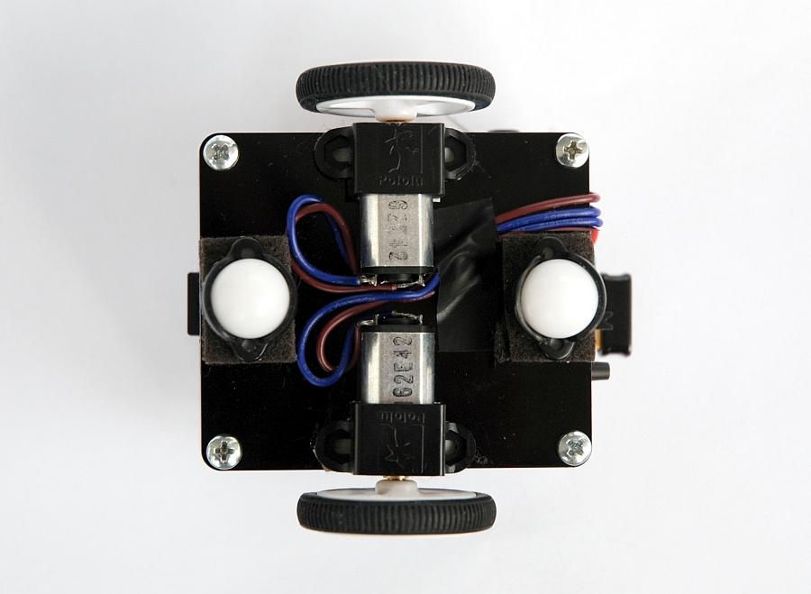
- Actuators / output devices: 2x 1:100 gear motors (Pololu)
- Control method: autonomous, iPhone Web App
- CPU: Raspberry Pi Model A+
- Operating system: Raspbian Wheezy
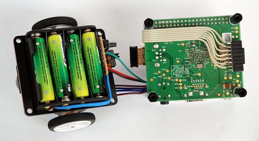
- Power source: 4 AAA battery
- Programming language: Bash, Python, PHP
- Target environment: indoor
Updates
2015-06-06: Update of tarball with software
2015-06-05: PiBot-A at Pi and More
2015-05-01: Software (complete)
2015-04-25: Web-App
2015-03-30: Maze solver: software
2015-03-29: Maze solver: video and description
2015-02-20: Maze follower: video (deleted)
2015-02-08: Line follower: video and description
2015-01-27: Assembly of the robot
2015-01-24: Obstacle avoider: video and description
Contents
Overview
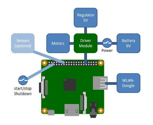
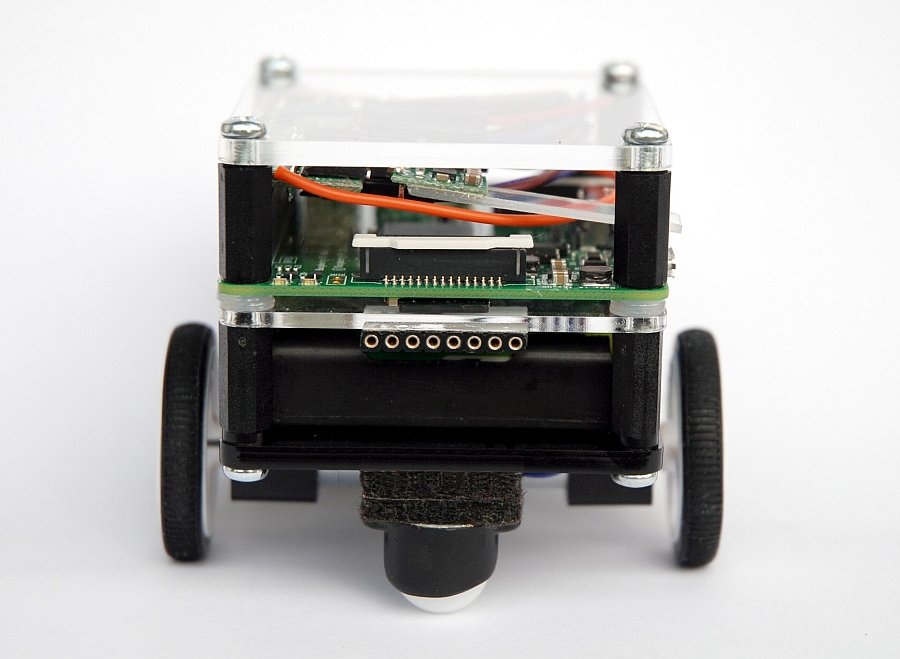
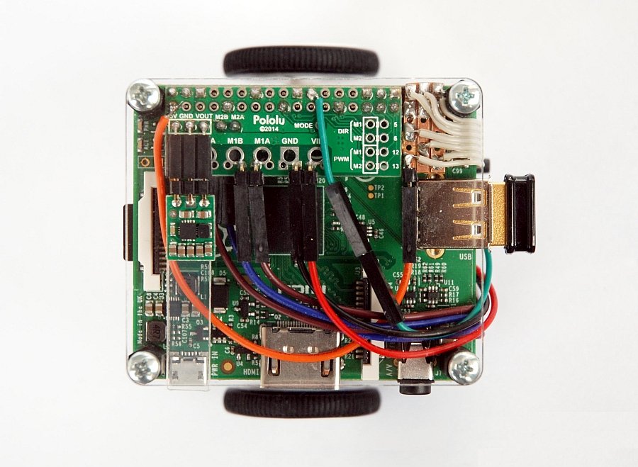
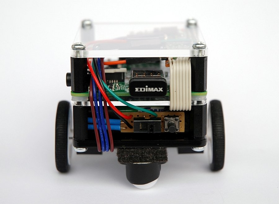
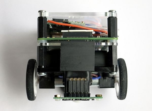
Most parts of the robot are connected to the GPIO port of the Raspberry Pi. The only exception is the WiFi USB dongle, which is used by a web-app for performing start, stop and shutdown, and for the selection of the operational modes of the robot (see below). It also provides a wireless SSH connection when I'm accessing the Raspberry Pi in non-mobile mode during development.
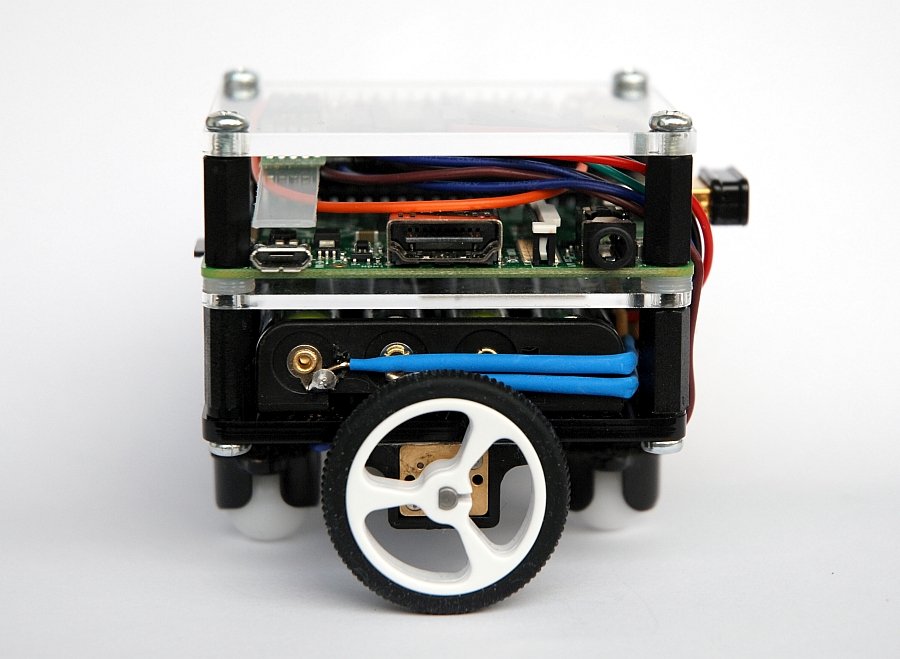
The motors are controlled (via PWM) by the "DRV8835 Dual Motor Driver Kit for Raspberry Pi B+" of Pololu (see component list below), which is rather new and works fine with Model A+, too. The board is connected directly to the GPIO connector and occupies pins 1 through 34 (although using only few of them).
The robot (motors and Raspberry Pi as well) is powered by 4 AAA batteries, a 5 V step-up/step-down regulator (connected to the Pololu module) provides 5 V to the Pi, which is fed into the Pi through the GPIO connector. In non-mobile mode I can disconnect the regulator mechanically and plug a wall wart into the Micro USB Port of the Pi.
A single button switch is attached to one GPIO pin and GND. It toggles between start and stop and performs a shutdown when pressed longer than 2 seconds.
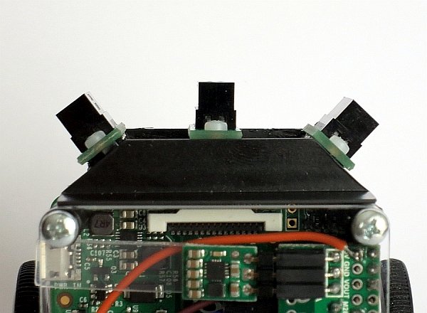
I also attached a female 8 pin connector at the front of the chassis and wired it with 3V3, GND, and a handful of GPIO pins. Varying sensors can be mounted here to implement different behaviors like obstacle avoidance or line following.
NOTE: Since the sensors are optional, the robot can be operated without them (e.g. with some simple remote control). In this case the hardware is plug and play, and the software needed (a python library) is already part of the Pololu module kit. The additional software I wrote is easy to understand (only few scripts). For this reason I think this project is pretty suitable for beginners or schools – if they refrain from the very compact design, which makes it rather difficult to build.
Web-App
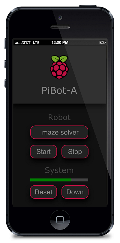
The web-app is a simple PHP web page, beautified through some CSS and optimized for my iPhone. The web server running on the Raspberry Pi is lightpd. The web-app provides the following functionality:
Section "Robot"
- Select the robot's operational mode (HTML drop-down list)
- Start and stop the robot
Section "System"
- Kind of "battery bar" (see below)
- Reset of the "battery bar" to status "full" after battery change
- Shutdown Raspberry Pi
The "battery bar" is actually an operating hours counter, that counts the minutes of operation after the last battery change from 150 to 0, since in my experience the robot can be operated for about 2 1/2 hours before the voltage is getting dangerously low. At 30% the bar becomes yellow, and at 10% and less it becomes glowing red.
After a change of the sensors the robot's operational mode must be set properly through the selector.
Construction
Chassis
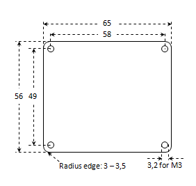
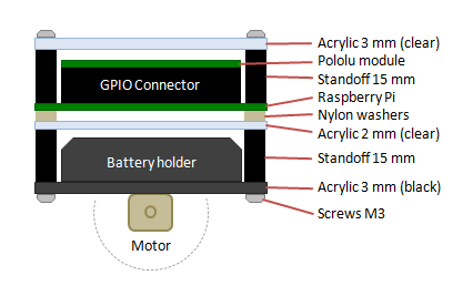
Main parts of the robot chassis are 3 acrylic plates exactly sized as the Raspberry Pi board. I purchased them from Nordic Panel (in Germany, see list of components below). Since I wanted to use common M3 threaded distant bolts, I had to drill out the mounting holes in the Pi's board to 3.2 mm, which of course results in a loss of warranty. If you don't like this you have to get M2.5 threaded parts.
Assembly
The assembly of the chassis is shown in the picture above.
 |  |  |
 |  |  |
(Click photos to enlarge)
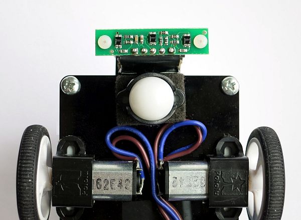
The photos above show the assembly of all parts. The motors and the ball casters are stucked under the ground plate with double sided glue tape, just as the battery holder on the opposite side. The on-off switch and the start-stop-shutdown button are mounted on a small board at the front side of the battery holder. Seven wires are leading from motors and switches to the upper floor of the construction, and are connected to the Pololu module board.
The 8 pin sensor connector is mounted under the middle acrylic plate (with glue tape, too) and connected with the GPIO connector on the upper floor through the grey ribbon cable. The very ugly thing besides the Pololu board is my DIY 6 pole GPIO plug.
Software
The whole software is implemented with high level script languages. The different operational modes are stored persistently in a config file "robot.cfg", the currently active mode is marked by a "1":
 0 oa obstacle avoider
 1 lf line follower
 0 ms maze solver
 0 rt robot test
The active mode and the sensors plugged into the sensor connector must match when the robot starts operation. As long as both is left unchanged or changed simultaneously the robot can be started immediatelly after boot since the appropriate operational mode is defined statically in robot.cfg. The different operational modes are implemented by separate Python scripts that import the basic functions for motor control from the Pololu python library that is provided along with the "DRV8835 Dual Motor Driver Kit for Raspberry Pi B+". For example, the script for the obstacle avoider ("oa") is "robot-oa.py".
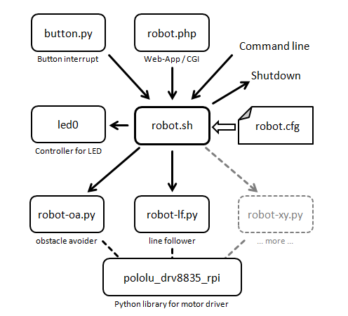
Central component of the software is the bash script robot.sh. Its main purpose is to
- setup the operational mode in config file robot.cfg
- start/stop the robot by involving the appropriate Python script
- reset the operating hours counter after battery change
- shutdown the Raspberry Pi
It also controls the green status LED of the Raspberry Pi, which is used as an indicator of different operating states, and it resets the operation hours counter. (The operation hours counter is a cronjob not shown in the above diagram, see script runtime++ below.) The script robot.sh must be executed as root (via sudo). It can be started from the command line, through the start-stop-shutdown button or by the web-app.
Listings of all scripts:
| Main bash script: | robot.sh |
| Button interrupt: | button.py |
| Web-app PHP: | robot.php |
| Web-app CSS: | robot.css |
| LED controller: | led0 |
| Runtime counter: | runtime++ |
| Obstacle avoider: | robot-oa.py |
| Line follower: | robot-lf.py |
| Maze solver: | robot-ms.py |
Download
All scripts can be downloaded here (gzipped tarball): PiBot-A.2015-06-06.tgz
Modes of Operation
Obstacle Avoider
 |  |  |
(Click photos to enlarge)
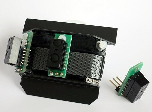
For the operating mode obstacle avoidance I use Sharp infrared distance sensors, provided by Pololu, mounted on tiny boards (see photos and component list below). I attached 2 sensors that are sensing distance to 5 cm at the front edges with an angle of 45°, and a 10 cm type in the middle. The sensors are mounted on a self made carrier (see photos above) that can be plugged into the sensor connector on the robot.
The software (robot-oa.py) is pretty simple, it implements the minimum of functionality that is needed for obstacle avoidance. (The video above is made with this software.)
Line Follower
 |  |  |
(Click photos to enlarge)
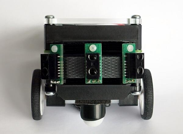
The line follower is realized with the Pololu "QTR-3A Reflectance Sensor Array" with three IR emitter and receiver (phototransistor) pairs. This array works very fine (see video), although
- its analog output is connected directly to the digital GPIO pins of the Raspberry Pi,
- it is operated with only 3V3 (rather than 5V, which is recommended), and
- it is geometrically optimized for 19mm electrical tape, but used with 15mm tape.
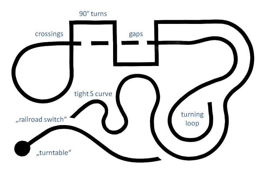
The course I created is presenting a few challenges, not to say tortures:
- Curves of different radii (also very, very tight)
- Several 90 degree turns
- Gaps in the track
- Crossings with and w/o gaps
- A turning loop
- A black disc as turning point (spot turn)
- "Railroad switches"
The software (robot-lf.py) is not a PID controller (I don't know how to implement that), but just a little bit logic to meet the challenges. Surprisingly it works pretty well (see video)!
Maze Solver
Maze solving robot with only 3 sensors
For the maze solver I use the same sensors as for the line follower. That means I have only 3 sensors, rather than 5 or more, which seems to be usual. Notice that the robot is swaying a little bit whenever it reaches a node of the maze. It then looks to the left and the right to see whether there is a black line forking, a crossing or a T-junction. That way it compensates the absence of the outer sensors that are typically used for that purpose.
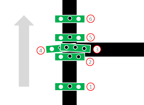
This works as follows (example, image above shows the moving sensors):
- The robot is driving just straight ahead.
- Reaching the node, robot thinks: I'm drifting to the left (right sensor is on the line), hence making a correction to the right.
- As a result: all sensors black, robot knows: I'm over some node, and I'm too far to the right (because of the last movements).
- Robot sways to the left, looking with left sensor whether there is a line. No line found: robot knows, a line is branching to the right.
- Robot corrects its direction by turning back to the right a little.
- Robot drives behind the node until the node is under the axle in the center of the robot. It now sees a line. Robot knows: the node was a T-junction right. In this position the robot decides on where to move and eventually will turn on the spot.
The timing is very crucial: it makes a big difference to drive some hundredths of seconds when the battery voltage is going up and down. Hence the robot starts with a 360° turn to the left and right and back performing some calibration (see video). The time needed for this is measured and is taken into account when calculating the time for some particular movement.
Strategy for solving the maze
- The target (the black disk) is placed anywhere in the maze.
- The robot is placed anywhere in the maze.
- Robot searches and finds the end point following the left-hand rule.
- Robot calculates the shortest path by an algorithm similar to dead-end filling.
- Robot drives along the shortest path back to its starting position and "nods its head".
A second video with different positions of start and end point can be viewed HERE.
Software
The software is here: robot-ms.py
Lists of Components
Robot base
| Component | Product | Manufacturer | Distributor (DE) |
|---|---|---|---|
| Raspberry Pi | Raspberry Pi Model A+ | Raspberry Pi | Watterott |
| Motor control | DRV8835 for Raspberry Pi B+ | Pololu | Exp-Tech |
| 5V regulator | Pololu S7V7F5 | Pololu | Exp-Tech |
| On-off-switch | Sliding switch 1 x on/on | unknown | Conrad |
| Start-stop-button | Button 24 V/DC 0.05 A T604 | unknown | Conrad |
| Robot chassis | Acrylic plates | Nordic Panel | Nordic Panel |
| Spacer bolts | 15 mm M3 thread female/female | Schäfer | Conrad |
| Spacer bolts | 15 mm M3 thread female/male | Schäfer | Conrad |
| Battery holder | Battery holder L for 4 Micro | Wentronic | Conrad |
| Motors | 100:1 Micro Metal Gearmotor | Pololu | Lipoly |
| Motor brackets | Micro Metal Gearmotor Bracket | Pololu | Exp-Tech |
| Wheels | Pololu Wheel 32x7mm | Pololu | Exp-Tech |
| Ball caster | Ball Caster with 1/2" Plastic Ball | Pololu | Exp-Tech |
| WiFi dongle | Edimax EW-7811Un | Edimax | Amazon |
Sensors
| Component | Product | Manufacturer | Distributor (DE) |
|---|---|---|---|
| Obstacle Avoider | Digital Distance Sensor 5 cm | Pololu | Exp-Tech |
| Obstacle Avoider | Digital Distance Sensor 10 cm | Pololu | Exp-Tech |
| Line Follower | QTR-3A Reflectance Sensor Array | Pololu | Exp-Tech |
Based on Raspberry Pi Model A+, moving autonomously, obstacle avoiding, line following, maze solving, Braitenberg vehicle