Phototropic Bristlebot
UPDATE: ADDED VID WITH NEW EYES AND SOME THOUGHTS AT THE BOTTOM.
One of my lower priority robots but thought I'd post it up for scrutiny anyhow. My plan is to use a pair of bristlebots made of common toothbrushes differentially driven by a photosensitive MSE setup.
Project plan:
- Assemble single bristlebot to test efficacy of component choices. √
- Fabricate a vibration-dampening "aka" to link the two britlebots. √
- Attach phototropic circuitry and solar cell. √
- Hammer out the kinks in the final design.
- Place robot in the sun, crack a beer and take a video for LMR!
Action starts at 0:15! -->
Materials:
- Super expensive Colgate Pro-something-or-other toothbrushes
- 4700uF 16V capacitor
- 1381J 1381S voltage triggers
- 7V 4mA solar panel from Three-LED solar keychain from eBay 5.5V @ 50ma solar panel
- 2N2222 NPN transistor
- 1N5818 Schottky diode
- 0.1uF 0.47uF timing capacitors
- SPST switch
- BPW34 SFH-205f "eyes"
- Miniature vibrating pager motors
Photolog:
- Assemble single bristlebot to test efficacy of component choices.
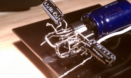
Freeformed MSE in progress:
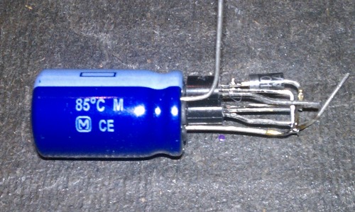
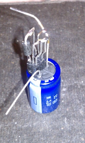
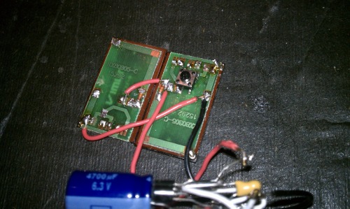
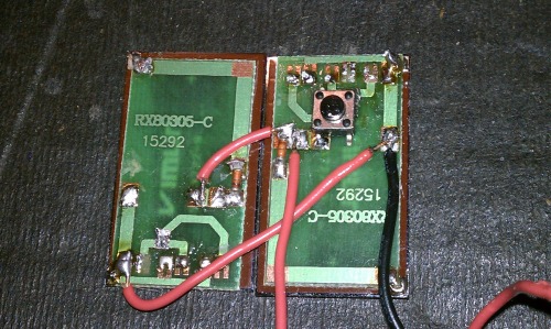
The single solar panel was not enough to keep the motor firing enough on the breadboard so I doubled them up:
I superglued a scrap piece of plastic to the back of the toothbrush head to have a nice flat surface to tape the MSE to:
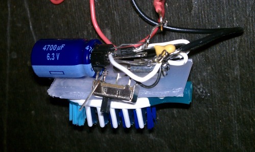
I cut out the middle row of bristles that pointed in the wrong direction (the green and white parts, hard to see). A PITA that I'm not entirely sure is necessary:
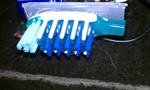
Some simple electrical tape to hold the panel on and shazam!:
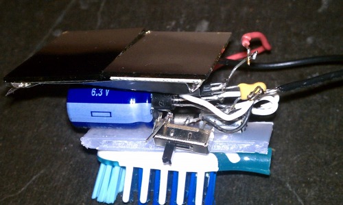
2. Fabricate a vibration-dampening "aka" to link the two britlebots
I used some Parafilm, a cardstock box I made (2"x1.5"x0.25"), and some clear silicone sealant.
A shot of the tray lined with Parafilm:
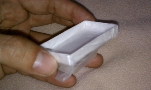
A pre-stretched and post-stretch comparison for those unfamiliar with Parafilm:
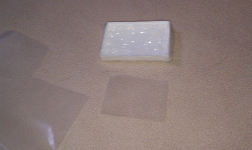
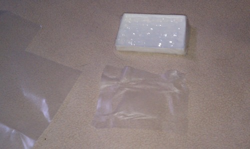
I took the stretched out film and molded it to the backs of the brushes. They have some studding that I wanted to use to align the brushes. I dropped the whole thing on the top, smoothed out some bubbles, then sank the MSE in the middle of the goo:
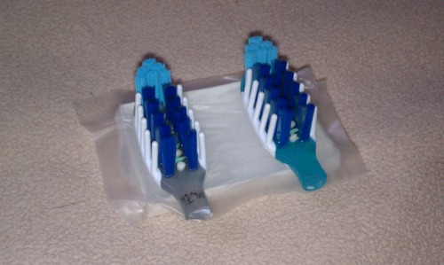
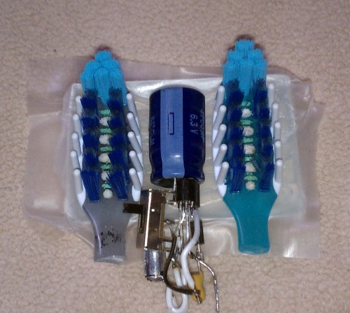
Just like with all presents, I couldn't wait to open it, and I ended up messing up the casting slightly because it wasn't fully cured. But it will work:

The brushes sit in their little pockets nicely and I got the general depression I wanted for the capacitor to sit in. It's not nearly as flimsy as I thought it would be, and it might actually transfer too much vibration. I saved the cardstock box just in case I need to make a thinner one.
3. Attach phototropic circuitry and solar cell
Some pics of the progress:
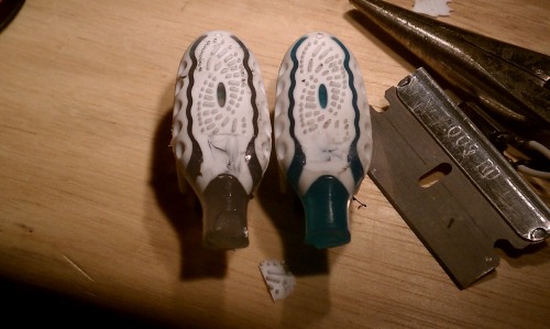
Both MSE's ready for the motors (left), The modified aka with cuts to stow away the rotational weights on the motors (right)
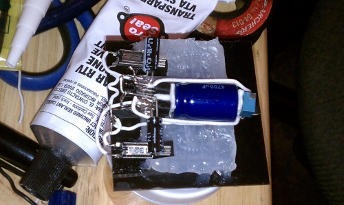
I had to cut some of the rubber away to allow the weights to rotate freely.
A couple pics of the operational bot without tactile feelers.
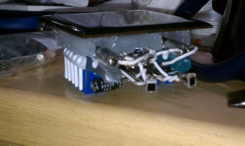
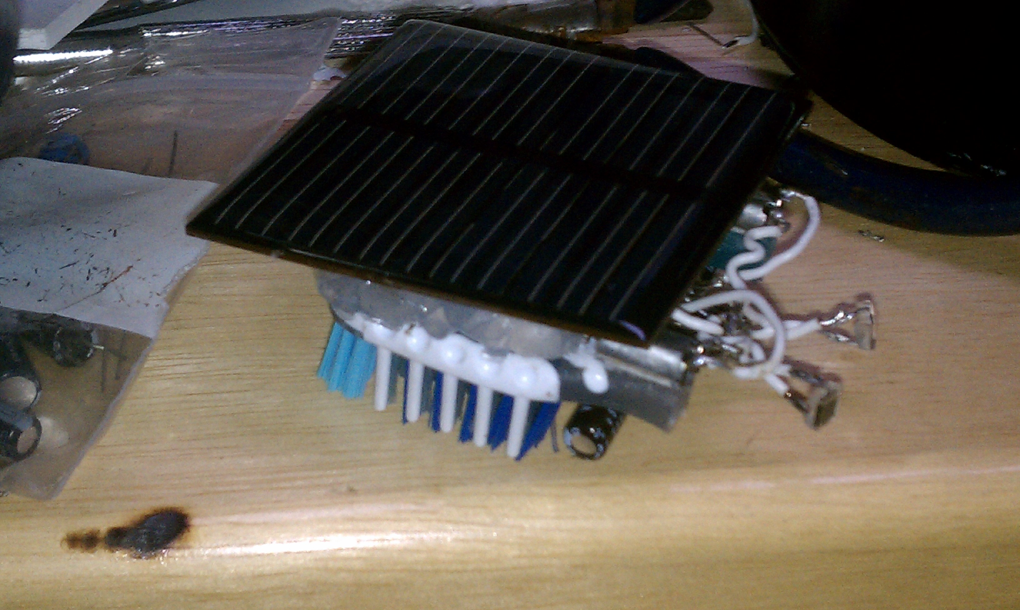
4. Hammer out the kinks in the final design
Per usual, the robot is not spot-on right out of the gate. Usually MN1381's have some variance between them when it comes to the voltage they trigger at. The 100K pot is used to bias the two Miller solar engines to bring them in balance.
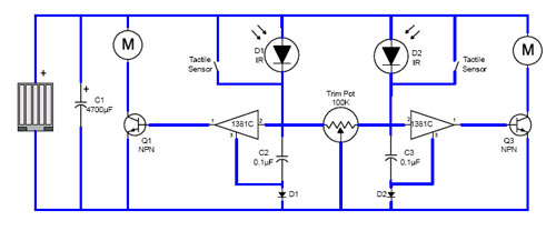
Unfortunately, even with all the resistance dialed to one side, only the one MSE will fire. I tested the two assembled MSEs on the breadboard separately and there didn't seem to be a drastic difference between the trigger levels at that point. I'm leaning towards the idea that my wiring got fouled up on the way to the final product :sigh: Freeforming can be a bear sometimes. I still need the feelers from Solarbotics as well. Hooking them up is designed to be easy. I planned ahead.
That being said, it does a predictable little do-see-do to the left constantly in bright sunlight. The solar panel would be better with 6V but it is a semi-functional bot (needs absolutley full sunlight). I'm going to do a little troubleshooting with the unresponsive left engine and hopefully all will pan out. I will also shoot a vid when the lady friend isn't insisting on my recently lacking attention.
Don't ignore the g/f...
UPDATE (Oct. 24, 2010):
As you can see in the pictures I didn't shield the photoeyes in any way. After wrapping some strips of electrical tape around them the robot started working like I thought it would. I shot a vid and posted it. I will get to those feelers now ASAP since this robot is nearing full completion muahahhaa!
UPDATE (May 15, 2011):
At some point last year I put IR shielded SFH-205f eyes on the vibrobot and then the weather went sour, as far as solar projects are concerned. Shot a vid of the first outdoors test of the beasty between primering parts and drilling holes in a chassis. I think I need to add a little shielding as these photodiodes have a pretty wide field of view. I don't like how its own shadow can confuse it. Still no tactile feelers. a work in progress to this date!
Vibrate around phototropically with tactile feelers
- Actuators / output devices: Vibrating pager motors
- Sensors / input devices: photodiodes, tactile switches
- Target environment: indoor flat surfaces, Full sunlight


