


Object Avoiding Arduino Robot
hello guys...
this is our project..thats called object avoiding robot..
this one basically arduino based ic controlled by ultrasonic distance sensor..
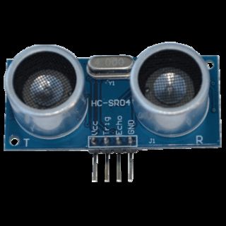
An Ultrasonic sensor is a device that can measure the distance to an object by using sound waves. It measures distance by sending out a sound wave at a specific frequency and listening for that sound wave to bounce back. By recording the elapsed time between the sound wave being generated and the sound wave bouncing back, it is possible to calculate the distance between the sonar sensor and the object.
Step 1:-components
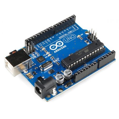
1:-arduino uno
2:-ultrasonic distance sensor(hc-sr04)
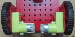
3:-two dc motors
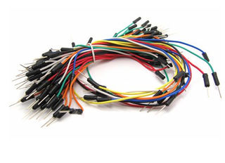
4:-jumper wires
5:-mini breadboard
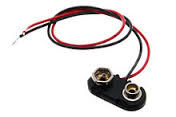
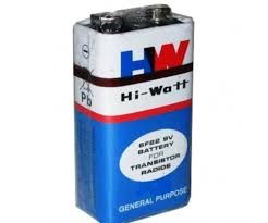
6:-9v battery with jack
7:-l293d motor driver
8:-two wheels and caster wheel
Step 2:-working Principle
Before going to working of the project, it is important to understand how the ultrasonic sensor works. The basic principle behind the working of ultrasonic sensor is as follows:
Using an external trigger signal, the Trig pin on ultrasonic sensor is made logic high for at least 10µs. A sonic burst from the transmitter module is sent. This consists of 8 pulses of 40KHz. The signals return back after hitting a surface and the receiver detects this signal.
The Echo pin is high from the time of sending the signal and receiving it. This time can be converted to distance using appropriate calculations. The aim of this project is to implement an obstacle avoiding robot using ultrasonic sensor and Arduino. All the connections are made as per the circuit diagram.
The working of the project is explained below. When the robot is powered on, both the motors of the robot will run normally and the robot moves forward. During this time, the ultrasonic sensor continuously calculate the distance between the robot and the reflective surface. This information is processed by the Arduino.
If the distance between the robot and the obstacle is less than 15cm, the left wheel motor is reversed in direction and the right wheel motor is operated normally. This will rotate the robot towards right. This rotation continues until the distance between the robot and any obstacle is greater than 15cm. The process continues forever and the robot keeps on moving without hitting any obstacle.
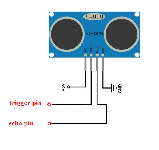
Step 3:-distance Sensor Connection
here.
ultrasonic sensor
vcc is connect to +5v
gnd is connect to gnd
trig and echo pin is connect to arduino pin.
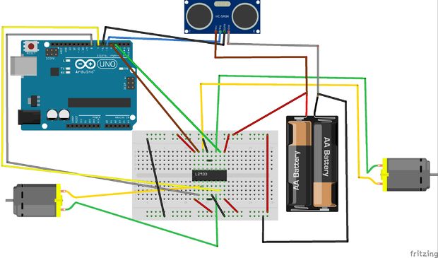
Step 4:-circuit Diagram
here
ultrasonic distance sensor:-
vcc------+5v
gnd---------gnd
trig pin--------connect 5pin of the arduino
echo pin--------connect 6pin of the arduino.
and 8,7,4,and 3pin are connected to motor driver l293d
8pin of arduino connect..........2pin of l293d
7pin of arduino connect----------7pin of l293d
4pin of arduino connect------------10pin of l293d
and 3pin of arduino connect------15pin of l293d
Step 5:-if You Used As L293d Ic
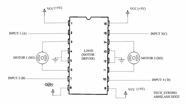
if you use l293d ic instead of l293d motor driver..
even its will be easy for connection.... l293d ic have 16pin... 1,8,9 and 16 pin connect to +5v.
and 4,5,12,13 pin connect to gnd...
input 1,2,3 and 4pin is connect to arduino pin..
output is connect to left motor and right motor..
input 1 and 2 is connect for left motor..
and input 3 and 4 is connect for right motor..
Step 6:-uploading the Code
here belew the code.....
just copy and paste to the arduino..and compile 1st then upload to arduino board.
const int trig = 5;
const int echo = 6; const int leftForward = 8; const int leftBackward = 7; const int rightForward = 4; const int rightBackward = 3;
int duration = 0; int distance = 0;
void setup() { pinMode(trig , OUTPUT); pinMode(echo , INPUT); pinMode(leftForward , OUTPUT); pinMode(leftBackward , OUTPUT); pinMode(rightForward , OUTPUT); pinMode(rightBackward , OUTPUT); Serial.begin(9600);
}
void loop() { digitalWrite(trig , HIGH); delayMicroseconds(1000); digitalWrite(trig , LOW);
duration = pulseIn(echo , HIGH); distance = (duration/2) / 28.5 ; Serial.println(distance);
if ( distance < 20 ) { digitalWrite(leftForward , LOW); digitalWrite(leftBackward , HIGH); digitalWrite(rightForward , HIGH); digitalWrite(rightBackward , LOW); delay(100); } else { digitalWrite(leftForward , HIGH); digitalWrite(leftBackward , LOW); digitalWrite(rightForward , HIGH); digitalWrite(rightBackward , LOW); }
Step 7: Step 7:-applications
1:-Obstacle avoiding robots can be used in almost all mobile robot navigation systems.
2:-They can be used for household work like automatic vacuum cleaning.
3:-They can also be used in dangerous environments, where human penetration could be fatal.
Step 8:-result
so guys this link also help you to build this project easily...
follow this link and also our channel s_r tronics..
https://www.youtube.com/watch?v=Bm9H65yu7Zw
soooooo subscribe our channel to stay tuned with us..and likes also and do comment in inbox ....