


NO-PANTS STEVE + DIY R/C Tx 2.4GHz unit
NO-PANTS STEVE formerly know as STEVE II and even before that it was known by its true (but as it seems tongue-twister of a) name SRCMPIBDUSBNRTBAPOJTTBASOH (-- Shoddy Remote Controled Mobile Platform Initially Being Developed Under Secrecy But Now Revelead To Be A Pile Of Junk Trying To Become A Sort Of Hoovercraft), or Styrofoamy meets Grocery Bag, or just Steven (or Steve I) for close friends (only).
&
DIY R/C 2.4GHz TX unit
Approach/Objectives:
Following my "sacred tenets" of material usage, for the duration of this project I tried to build a vehicle from scratch using "cheap ass" materials and whatever I might find at "arms' reach" (household items and whatnot) whenever feasible. The engineering of it despite the (non-disclosed) research I've done was done mostly on-the-fly, i.e. engineering decisons were mostly done in an ad hoc manner. Almost the same applies to the TX (although I mean it to be re-usable for other projects). Despite this, I've already decided that this TX unit will be: first, a learning experience and second, a prototype into a subsequently designing a better DIY nRF24L01+ based TX unit (which will hopefully will be more ergonomic!).
TO DO:
- Improve ESC arming/calibration routine (or just order another ESC).
- Improve skirt's aft side (or later maybe make a new skirt with more resilient material)
- (Backed off from the idea of implementing reverse)
- Have fun hovering it around :D
-
-
-
-
-
-
-
-
-
-
-
-
-
-
-
-
-
-
-
-
-
-
-
-
-
-
-
-
-
-
-
-
-
-
-
-
May, 18th 2013
- Added the code for the Remote Control (Transmitter) and for Steve NO-PANTS (Receiver).
- Added a DXF (LibreCAD) template file for Steve's skirt panels.
(To understand it you need to know how to work with a CAD tool and refer to here).
- Added the proper spelling soundbyte for Steve's true name. (for lumi :P)
- I now consider (NO-PANTS) Steve (the Second) as COMPLETE.
- Steve's (receiver node) CODE (transmitter code is at its section down below):
// Lovely code that (mostly) forces
// Steve to do my devious biding!
#include <Servo.h>
#include <SPI.h>
#include "nRF24L01.h"
#include "RF24.h"


/* ------------- TRAVELLING DATA STRUCTS -------------- */

// commands goes inside
typedef struct{
  int X;
  int Y;
  boolean buttons[4];
}
Payload;

// feedback goes inside
typedef struct{
  int rudderAng;
  int Z;
  int S;
}
Feedback;

/* -------------- DEBOUNCING VARIABLES ------------------------- */

long previousMillis = 0;        // timer for servo
long previousButtonMillis = 0;  // timer for buttons
//long previousTX = 0;            // timer for transmissions
//long TXinterval = 25;           // interval to transmit telemetry
const int interval = 30;        // interval to update servo
const int binterval = 70;       // interval for debouncing
const int TX_timeout = 100;     // remote - craft  link timeout

/* ------------------------------------------------------------- */


Servo thrust;
Servo lift;

Payload package;
Feedback telemetrics;

Servo rudder;

int oldAngle, newAngle = 0;     // servo positions

int lift_ang;                   // lift motor pseudo-'angular' velocity

int vel;                        // thrust pseudo-'angular' velocity

boolean run = false;

RF24 radio(9, 10);

const uint64_t pipes[2] = {
  0xF0F0F0F0E1LL, 0xF0F0F0F0D2LL };


/* ----------------------------------------------------- */


/* SET UP THE RECEIVER NODE */

void setup(void)
{
  Serial.begin(57600);

  radio.begin();
  radio.openWritingPipe(pipes[1]);
  radio.openReadingPipe(1,pipes[0]);
  radio.startListening();


  rudder.attach(7);

  // It is important to arm
  // EACH ESC sequentially
  lift.attach(5);
  armESC(lift);
  lift_ang = 50;

  delay(100);

  thrust.attach(6);
  armESC(thrust);
  vel = 50;
}

void loop(void)
{

  unsigned long started_waiting_at = millis();
  boolean timeout = false;
  while ( ! radio.available() && ! timeout )
    if (millis() - started_waiting_at > TX_timeout )
      timeout = true;

  if ( timeout ){
    //Serial.println("Failed, response timed out.");
    run = false;
  }
  else{
    radio.read( &package, sizeof(package) );
    run = true;
  }


  // if TX-RX link is alive () then...
  if(run)
  {

    /* ------------ RUN RECEIVED COMMANDS ---------------- */

    int X = package.X;
    int Y = package.Y;


    // RUDDER CONTROL
    // ------------------------------------------------------------
    if (X > 480 && X < 530 ){
      newAngle = 90;             // 90 = servo in center position
    }
    if (X < 480){
      newAngle = (map(X, 480, 155, 91, 150));
    }
    if (X > 530){
      newAngle = (map(X, 530, 815, 89, 30));
    }

    // FORWARD THRUST CONTROL... VROOOOMMMMMMM
    // ---------------------------------------------------------------------
    if (Y > 550 && Y < 635 ){
      thrust.write(50);           // neutral position -- motor not spinning
      telemetrics.S = 50;
    }
    if (Y >= 635){
      vel = (map(Y, 635, 925, 60, 90));
      thrust.write(vel);
      telemetrics.S = vel;
    }

    unsigned long currentMillis = millis();

    // Issue rudder repositioning command only if desired
    // position changes and (debouncing) interval is over
    if(oldAngle != newAngle && currentMillis - previousMillis > interval) {
      previousMillis = currentMillis;
      oldAngle = newAngle;
      rudder.write(newAngle);     // tell servo to go to position in variable 'pos'
    } // close if millis-land (for rudder servo)


   // HANDLE BUTTON PRESSES
   // ------------------------------------------------------------------
   currentMillis = millis();

   if (currentMillis - previousButtonMillis > binterval) {

      // button press for instant MIN (none) lift speed (NO throtle)
      if (package.buttons[0] == 1){
        lift_ang = 50;
      }
      // button press for lift speed INCREMENT
      if (package.buttons[1] == 1){
        if( lift_ang < 120 ){ lift_ang += 5; }
      }
      // button press for instant (sort of) "stationary safe" hovering
      if (package.buttons[2] == 1){
        lift_ang = 90;
      }
      // button press for lift speed DECREMENT
      if (package.buttons[3] == 1){
        if( lift_ang > 50 && lift_ang <= 115 ){ lift_ang -= 5; }
      }

      previousButtonMillis = currentMillis;

      lift.write(lift_ang);

   } // close if "millis-land" (secundary test) -- button millis debounce


    /* ---------------------------------------------------------------------- */

    // Set telemetry data to send
    telemetrics.Z = lift_ang;
    telemetrics.rudderAng = newAngle;


  } // close "if(run)" statement
  else{
    //Serial.println("No radio available");
    emergencyStop();
  }

  // TO transmit TELEMETRICS use this:

  radio.stopListening();
  bool ok = radio.write( &telemetrics, sizeof(telemetrics) );
  radio.startListening();


  // OR this: (need to uncomment variables previousTX & TXinterval
  //           if using this option)

//  unsigned long currentMillis = millis();
//
//  if(currentMillis - previousTX > TXinterval) {
//    previousTX = currentMillis;
//
//    radio.stopListening();
//    bool ok = radio.write( &telemetrics, sizeof(telemetrics) );
//    radio.startListening();
//  }


} // close the "loop()" block


// Accessory functions

void emergencyStop()
{
  thrust.write(50);
  lift.write(50);
}

void armESC(Servo esc)
{
  esc.write(10);
  delay(2000);
  esc.write(50);
  delay(1000);
}
March, 24th 2013
OK, since Friday evening I started to actually like the new Steve. After all it wasn't so bad as it initially seemed to be...
Thus given that Saturday wasn't raining I decided take Steve for a "stroll" outside...
...at first he wasn't being able to handle outside too well, lesser speed and greater grip than it had inside,
so after the first "stroll" I decided to increase the maximum power delivered to the motors and went back for more...
and SUCCESS \o/ alas... handling a remote a cellphone camera at the same time is not very easy, so I was unable to shoot proper videos...
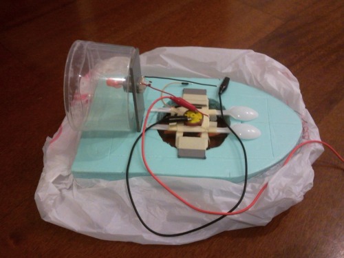
But one day, a plastic spoon and lots of double side tape later and I had this:

Hurray, now I was able to shoot video just by aiming the remote at the hovercraft while controling it, much easier to take video this way :P
So, now at the top of the page you can see TWO of the latest videos...
And here's an extra link for the "second run over water" --> http://youtu.be/aeTRFuKb_Vo
and the unlisted link for the "Don't start your hovercrafts on water if they have leaks in their skirts" video can also be found below :P
http://www.youtube.com/watch?v=f16gRchODtA
And thus, all my expectations where met with Steve and some even overcome, so now all that remains is some minor tweaks and maintenance...
March, 21th 2013
Well, it has been a long week, and I spent most of my free time and long nights working around improving the hovercraft skirt...
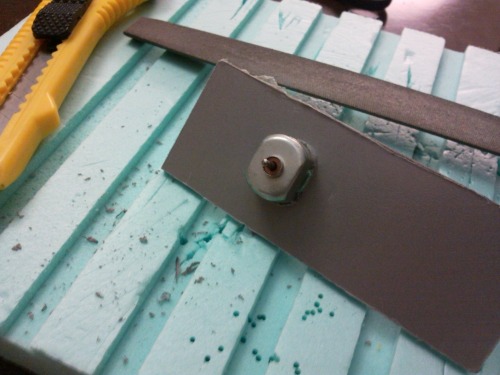
So, after learning a bit of LibreCAD on Sunday I managed to have a set of paper molds (1) for the skirt panels ready by Monday/Tuesday late night...
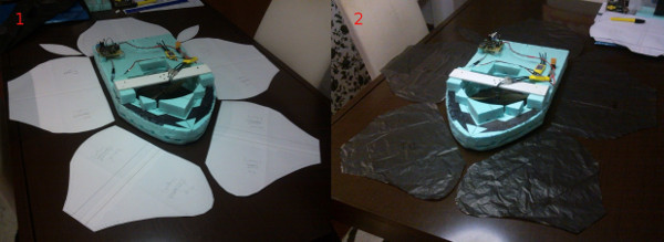
...and on Tuesday evening I've cut out some panels out of plastic trash bag (2). And so I've used those to make a quick slapped together mock skirt to see it it worked...
it was more troublesome to put this skirt together than it looks, the flimsy and slippery nature of the plastic gave quite the trouble to attach using clear tape... but in the end and overall... it actually worked and did not look too bad... EXCEPT the nose (1) which looked hideous.... but a bit of tweaking of the nose join seemed to have resolved that (2) to some extent...
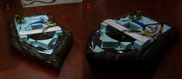
Wednesday evening... finally I decided to start with the actual skirt, so I cut the panels out of the final ripstop nylon, and unboxed a sewing machine that had never been used before, not by me not by anyone.... so a quick sewing 101 was required... with some manual reading, google searches, Diana tips via Ossipee, JerZ tips a few long hours I managed to get sewing ending up on this (2)

the nose joint I've left unsewn, both because when I got there was veeerryy late and because I was foreseeing trouble there...
...so Thursday evening arrives... some duct tape and a couple of hours later I get this...

...disappointing ...the nose skirt crosssection fold was narrower than the rest, and it took me quite a while to duct tape it in the most decent shape I could get from it.... even at crazy spin lift fan speed (where the hover goes spinning like crazy) did the skirt inflate-off those wrinkles..., it's still tail-heavy and now the front side is awful.
Only the directional control seem to have improved somewhat... and well... not the ugly skirt is supposedly more resilient... so maybe I could take Steve outside one of these day... and accidents... happen... Oops :|
March, 16th 2013
With the intention of improving my skirt design I was perusing through the interwebs when I came upon this site:
http://www.astounding.org.uk/ian/hovercraft/index.html (pretty nifty) so I've committed and ordered some ripstop nylon (one of the fabrics recommend to use as skirt material in RC hovercrafts). Since the nylon came from the UK it arrived fairly fast.
So, my hover design is somewhat different from the one I've found above, but thinking I could manage to adapt the instructions to my particular design I've started with some structure modifications.

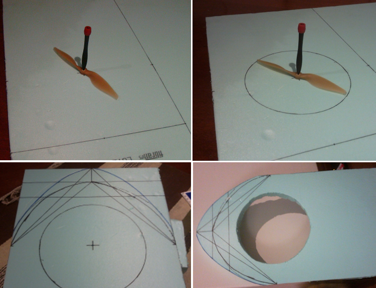
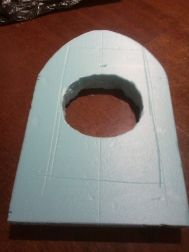
1 - So I started to cut another piece of styrofoam with the same shape as Steve, and afterwards sliced it transversely in half. The reason for the transversal slice was that I did not want to turn Steve into a "fat sandwich"... but in hindsight I just went to too much trouble and it would certainly not matter at all to use the full length styrofoam board. Also since now the bottow surface is quite ugly, oh well... hopefully it won't be seen often :P
2 - Cutting some extra paths for air flow within what would be the hovercraft's plenum chamber.
3 - Double side tape applied! (Contact glue eats through styrofoam, hot glue cools too fast, water-based glue is slow... and water soluble... and I did not have anymore types of glue at hand)
4 - And finally the deck is doubled after previously having unskirted Steve. I've re-skirt him just for a quick test and hovering was still working without any new issue.
Since I was handling styrofoam I've also taken the chance to rework the thrust motor/fan assembly. Re-aligned parts and built everthing into a more handy modular unit:
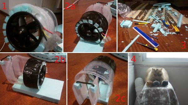
1 - Stuffing, building...
2 - Vanity shots
3 - Working with styrofoam can be messy....
4 - Cat overseer and mechanical mouse minions disapprove of the messy floor...
Also, following the instructions found on site previously mentioned I started to make my own mold panels to make my own custom skirt. For that I've watched a few tutorials on youtube to get me started with LibreCAD, more on that to follow...
February, 27th 2013
Was aiming at re-working the whole tale section, however I was being to slow and lazy and ended up just re-working the servo-to-rudder attachment. After that (and recharging the LiPo) I've tested it and made a new video (now featuring at the top of the page).
Testing was meant to see how did the new ESC and rudder connection improvements held and they held pretty good indeed, however more hardware tweaking has to be done in order to improve its controlability.
February, 26th 2013
- New ESC arrived today... and it only took one week out of Hong Kong *jawdropping*, right? Anyway I got to business and replaced that acursed HobbyKing ESC (which I sure is fine for native R/C setups) and replaced it with the new Mystery ESC (one just like the thrust motor attached ESC).
- Tweaked the code to account for the new ESC and while I was at it diminished the lift motor speed increments/decrements from 10 to 5.
- A quick testing let me confirm that now it's a breeze to get Steve up and ready to run after powering up. However, the LiPo alarm started beeping (I've also increased the thrust maximum output) so I wasn't able to do much testing, I just hope after I recharge the LiPo it can then be able to handle the new setup.
- Also noticed (what I already suspected) that mounting the EDF (and assorted setup) higher up might be advantageous, while I'm at it I might re-work most of the thrust/rudders system...
February, 24th 2013
- New video added featuring steering tests after the tweak described below.
NEW TESTING VIDEO: http://youtu.be/wVtoJKyoS0M
- A little tweak of the left rudder position enabled Steve to turn portside. Further programming tweaking of how I acquire and process the X/Y values might improve turning capability (for both sides).
- HobbyKing ESC... still the same stubborn "&#&%$/&# ... waiting on another Mystery ESC I've ordered.
- Still haven't found out how to setup the Mystery ESC in order to make the thrust reversible.
- High lift power/speed sends Steve into clockwise or anti-clockwise drift spinning. The direction of the spinning depends on the center of gravity. I'm currently tweaking battery placement and might resort to ballast weights in order to shift/tweak the center of gravity.
- Considering making a new more robust and more uniform skirt so that I can take Steve out to play... my long and narrow hallway is not that good for more extensive testing :/
- Also contemplating redoing the whole EDF/rudders mount and align everything the most perfectly my instrumentation and skill allows (as opposed to the current eyeball measuring :P)
February, 19th 2013
Turns out my 3S 850mAh 20C LiPo could not deliver enough "juice" to both motors at the same time. The only alternative at hand was a 2S 1800mAh 20C LiPo... so after a while making an makeshift adapter (battery has T-plug) whereas I have none of that. And off I go to test it out... still I have to battle the activation of the lift ESC... and after a few mishaps and frustating plentiful minutes I managed to get it all ready to go...
...and it went, mostly to its own accord. It was even more difficult to steer than I anticipated, but I blame it part on my remote design, part in my lack of RC skills and part the in the ad hoc construction of the craft itself. It would be nice if I had more space to test it other than a narrow hallway an a bit of living room. Still, in the future I'll see what I can do about the aforementioned issues and perhaps will solve some of them.
February, 17th 2013
In the last couple of days, I went about correcting some of the flaws found in the first live "full" test. Hence, I refitted the EDF (it doesn't shot after the front anymore :P); increased the servo horn length (now I get full turning angles); increased attachment of lift motor mount (safety measure -- don't want it to fly off :P); re-routed the wires and assorted electronics (make it pretty and tidier); added a few dabs of hot glue here and there (sorry Markus :P -- rejoice Hoff :P).
Re-tested a little...and it's not to bad. Only needs 50% throttle to hover, has plenty of thrust power and turning power. Skirt could use some tweaking at the aft side. May implement reverse thrust later. Arming/calibration of the lift motor ESC needs serious improvement... it's possible to be done, but at an unreliable rates -- alternatively I just might order a new ESC.
February, 15th 2013
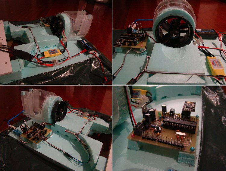
Well, since last time I've received the second ESC and EDF (Electric Ducted Fan) I've ordered, so a week or so ago I got back on the horse. I had some programming issues while implementing a two-way communication for the TX-RX units that held me back quite a few days... but ultimately got around them and now the remote-receiver node are working fine! After achieving reliable 2-way communication I've decided I could finally finish up the physical construction of the craft so a couple of nights ago I decided to start mounting the EDF and remaining electronics resulting on what you can see below.

Then, followed three tests... and alas and not surprinsingly couldn't manage to start the lift motor... that damned ESC is quite stubborn... surpringly though is that the second ESC (for the thrust motor) ran fine even without me activating the supposed arming routine...
Also, regarding rudder control (which I also been "upgrading") I will need a longer shaft to increase rudder angles... but that's fairly easy to achieve... as for the blasted HK ESC... wish me luck!
January, 6th 2013
So after receiving a new (now brushless) motor (EMAX CF2812) I're realized it did not match with any of the propellers I had (too small) and a couple more of propellers I got in the meanwhile where too big to the current frame (now dubbed Steve I). So, I let it go... some time has passed... a new year has come and a few nights ago I decided to try out controlling the aforementioned motor with a HK-20A ESC and my arduino... gave (and still does) quite the grieving... but since I managed to make it run, if only to some extent (a story for another day)... Upon, that limited success I decided to build a new frame roughly twice the size of the previous hovercraft... hence the new one shall be nickname, Steve II.
Below there are some photos that illustrate the making of Steve II, and also above is there a new video showing that Steve II can also hover.


October, 24th 2012
So, it's an HOVERcraft (I've told you it wasn't something new/revolucionary...just slightly uncommon) ... or it's trying to become one... well I'm trying to make it so. So, now that the cat is out of the bag, let's just re-open the bag because cats just love to sit inside bags and boxes.
NOTE: The craft's structural build presented below is now deprecated refer to it only for historical/cronological purposes. However, there's potential remote control development notes below (early days of this build log).
Steven (Steve I),
- hovering testing: https://www.youtube.com/watch?v=8iV8hNEINOc
- rudders testing: https://www.youtube.com/watch?v=TjSx44fmZro
It all started with a piece of styrofoam, dig a hole in it, shape a bullet-like nose...
A couple of plastic spoons, coffee stirrer sticks, a motor scavenged from an electric razor and a orange propeller later...
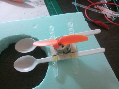
Fetch a nice groceries plastic bag out of the kitchen, and it's time for haut couture, so make a really nice skirt...
(only the second skirt worked acceptably)
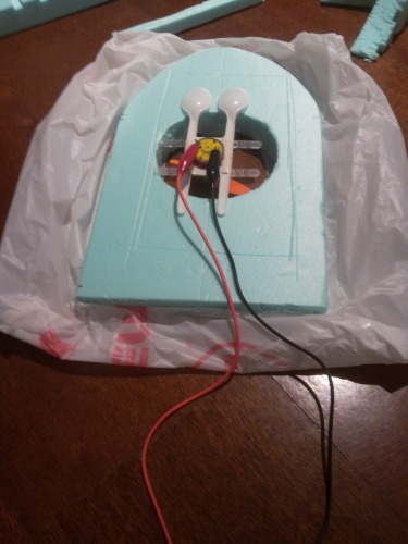
A bit more of Scotch tape, some PVC leftovers and you're ready to set the motor mount in place for a first hovering test...

So, ok... it can float around... now what? ah yes propelling it in a choosen direction would be nice...
In the meantime skillfully toast that motor by applying over 11V directly, get another same shape/size motor and work on getting a duct for the thrust/propelling fan... yes that empty olive container will do just fine...
Ok, so I better get some electronics and motor driver to see if I don't toast any more motors... (if only I knew better).
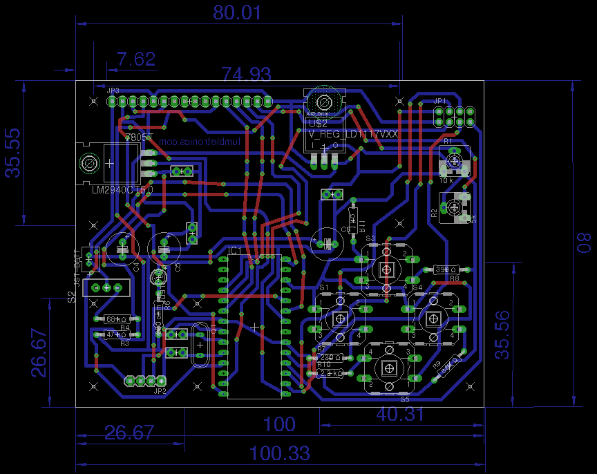
I went for TIP122/127 H-bridge to control the thrust motor (recently discovered to be quite energy inefficient for this particular application) and a simple TIP120 driver for the lift motor. I designed and constructed those myself from schematics available on the web. I also designed an produced a *duino based on the Bajduino 328 (by Bajdi). This "hoverduino" features 5V and 3.3V vregs, a voltage divider and an header for the nRF24L01+ radio module besides what you can expect from a nearly minimal *duino. See, boards nearly completed below.

Last night... while testing the lift motor with the TIP120 driver... I manage to somehow kill the lift motor... so now I need to look for a replacement (I have an handful of candidates around but must see if any can provide the airflow necessary to hover the "craft")
Meanwhile, I made a couple of rudders out of litter "sand" pack plastic container bits, cloth hanger wire and a straw. Picture not yet available, but they can be seen in the video where a 9g servo controlls them via signals received on the "hoverduino" sent by the "transmitterduino" package.
--- THE REMOTE ---
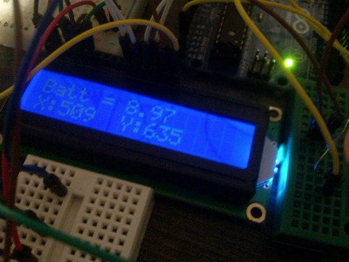
// include the library code:
#include <LiquidCrystal.h>
#include <SPI.h>
#include "nRF24L01.h"
#include "RF24.h"


/* ---------------------- MY CUSTOM-MADE 'ENVELOPE' STRUCTS ---------------------- */


// struct to carry
// lovely messages
typedef struct{
  int X;
  int Y;
  boolean buttons[4];
}
Payload;


// struct to get
// telemetric data
typedef struct{
  int rudderAng;
  int Z;
  int S;
  //double V;
  //int vroom;
}
Feedback;


/* ---------------------- BATTERY MONITORING RELATED VARIABLES ---------------------- */


// analog pin reading V_out/V2 from voltage divider
const int battPin = A5;

// default reference on circuit used (5.0, 3.3, 1.1)
const double refV = 5.0;
// How many volts does 1 ADC measure?
const double V_incr = refV/1024.0;

// values of resistances used for voltage divider
const double R1 = 68.4;
const double R2 = 46.6;

// determine voltage divider ratio
const double voltageRatio = (R2/(R1 + R2));


/* --------------------------- BUTTON-RELATED VARIABLES --------------------------- */

// button 'pad' pin
const int buttonPin = A3;

// Button setup schematics

//         Analog pin 5
//            |
//Ground--1K--|--------|--------|-------|
//            |        |        |       |
//           btn1     btn2     btn3    btn4
//            |        |        |       |
//         220 Ohm  390 Ohm  680 Ohm   2.2K
//            |--------|--------|-------|-- +5V

int j = 1;
// 'j' is the integer used in scanning the array designating column number
// these ranges below are dependent on the schematics above and may
// need to be adjusted manually to compensate for various factors
int Button[15][3] = {{1, 836, 840}, // button 1
                     {2, 732, 738}, // button 2
                     {3, 600, 625}, // button 3
                     {4, 310, 335}, // button 4

                     {5, 890, 900}, // button 1 + 2
                     {6, 870, 880}, // button 1 + 3
                     {7, 840, 860}, // button 1 + 4
                     {8, 810, 830}, // button 2 + 3
                     {9, 760, 780}, // button 2 + 4
                     {10, 665, 685} // button 3 + 4
                     };


int label = 0;            // for reporting the button label
int counter = 0;          // how many times we have seen new value
long time = 0;            // the last time the output pin was sampled
int debounce_count = 5;   // number of millis/samples to consider before declaring a debounced input
int current_state = 0;    // the debounced input value

int ButtonVal;

/* ---------------------------------------------------------------------------------------------------- */


// initialize the library with the numbers of the interface pins
LiquidCrystal lcd(8, 7, 5, 4, 3, 2);

// initialize radio with CE, CN pin numbers
RF24 radio(9,10);

const uint64_t pipes[2] = {
  0xF0F0F0F0E1LL, 0xF0F0F0F0D2LL };

// OUT-'pigeon'
Payload package;

// IN-'pigeon'
Feedback telemetrics;


long previousMillis = 0;
long interval = 25;


/* ---------------------------------------------------------------------------------------------------- */

/* SET THIS SHAITE UP !!! YEAAAHH!!! */

void setup() {

  Serial.begin(57600);
  radio.begin();

  radio.openWritingPipe(pipes[0]);
  radio.openReadingPipe(1,pipes[1]);
  radio.startListening();

  pinMode(buttonPin, INPUT);

  // set up the LCD's number of COLUMNS and ROWS:
  lcd.begin(16, 2);

}


/* ------------------------------------------------------------------------ */
/* ---------------- REPEAT THE CRAP BELOW ENDLESSLY ----------------------- */
/* ------------------------------------------------------------------------ */


void loop() {

  // monitor battery voltage on remote
  int val = analogRead(battPin);
  double battV = VoltageCheck(val);


  package.X = analogRead(A0);
  delay(1);
  package.Y = analogRead(A1);
  delay(1);


  /* ------------------- HANDLE BUTTON PRESSES -------------------------- */

  // If we have gone on to the next millisecond
  if (millis() != time)
  {
    // check analog pin for the button value and save it to ButtonVal
    ButtonVal = analogRead(buttonPin);
    delay(1);

    //Serial.println(ButtonVal);    // DEBUG

    if(ButtonVal == current_state && counter >0)
    {
      counter--;
    }
    if(ButtonVal != current_state)
    {
      counter++;
    }
    // If ButtonVal has shown the same value for long enough let's switch it
    if (counter >= debounce_count)
    {
      counter = 0;
      current_state = ButtonVal;
      //Checks which button or button combo has been pressed
      if (ButtonVal > 100){
      ButtonCheck();}else{

        package.buttons[0] = 0;
        package.buttons[1] = 0;
        package.buttons[2] = 0;
        package.buttons[3] = 0;}
    }
    time = millis();

  }


  /* --------------- RADIO 'TOWER' GROUND CONTROL -------------------- */


  if ( radio.available() )
  {


    bool done = false;
    while (!done)
    {
      done = radio.read( &telemetrics , sizeof(telemetrics) );
    }


    radio.stopListening();
    bool ok = radio.write( &package, sizeof(package) );
    radio.startListening();

  }


  /* ------------------- HANDLE LCD DISPLAY -------------------------- */

  /* LINE 1 */

  lcd.setCursor(0,0);
  // dirty hard-coded hack below
  if(telemetrics.Z < 100){
    lcd.setCursor(2,0);
    lcd.print(" ");
    lcd.setCursor(0,0);
  }
  lcd.print(telemetrics.Z);

  lcd.setCursor(6,0);
  // dirty hard-coded hack below
  if(telemetrics.rudderAng < 100){
    lcd.setCursor(8,0);
    lcd.print(" ");
    lcd.setCursor(6,0);
  }
  lcd.print(telemetrics.rudderAng);

  lcd.setCursor(12,0);
  if(telemetrics.S < 100){
   lcd.setCursor(14,0);
   lcd.print(" ");
   lcd.setCursor(12,0);
  }
  lcd.print(telemetrics.S);


  /* LINE 2 */

  lcd.setCursor(0, 1);
  lcd.print("X: ");
  lcd.setCursor(2, 1);
  lcd.print(package.X);

  lcd.setCursor(6, 1);
  lcd.print("Y: ");
  lcd.setCursor(8, 1);
  lcd.print(package.Y);

  lcd.setCursor(12,1);
  lcd.print(battV);

  /* --------------------------------------------------------------------------- */


}   // close loop()


/* ------------------------------ MOOOAAR HELPING FUNCTIONS ------------------------------ */


// read that battery voltage, biaaaatch
double VoltageCheck(int v){

  double pinV = v * V_incr;
  double volts_in = pinV * 1/voltageRatio;

  return volts_in;
}


// checks which f'king button (or combo of 2) has been pressed, if any...
void ButtonCheck()
{
  // loop for scanning the button array.
  for(int i = 0; i <= 10; i++)
  {
    // checks the ButtonVal against the high and low vales in the array
    if(ButtonVal >= Button[i][j] && ButtonVal <= Button[i][j+1])
    {
      // stores the button number to a variable
      label = Button[i][0];

      switch (label) {
          case 1:
            package.buttons[0] = 1;
            package.buttons[1] = 0;
            package.buttons[2] = 0;
            package.buttons[3] = 0;
            //Serial.println("button 1");
            break;
          case 2:
            package.buttons[0] = 0;
            package.buttons[1] = 1;
            package.buttons[2] = 0;
            package.buttons[3] = 0;
            //Serial.println("button 2");
            break;
          case 3:
            package.buttons[0] = 0;
            package.buttons[1] = 0;
            package.buttons[2] = 1;
            package.buttons[3] = 0;
            //Serial.println("button 3");
            break;
          case 4:
            package.buttons[0] = 0;
            package.buttons[1] = 0;
            package.buttons[2] = 0;
            package.buttons[3] = 1;
            //Serial.println("button 4");
            break;
          case 5:
            //Serial.println("button 1 + 2");
            package.buttons[0] = 1;
            package.buttons[1] = 1;
            package.buttons[2] = 0;
            package.buttons[3] = 0;
            break;
          case 6:
            //Serial.println("button 1 + 3");
            package.buttons[0] = 1;
            package.buttons[1] = 0;
            package.buttons[2] = 1;
            package.buttons[3] = 0;
            break;
          case 7:
            //Serial.println("button 1 + 4");
            package.buttons[0] = 1;
            package.buttons[1] = 0;
            package.buttons[2] = 0;
            package.buttons[3] = 1;
            break;
          case 8:
            //Serial.println("button 2 + 3");
            package.buttons[0] = 0;
            package.buttons[1] = 1;
            package.buttons[2] = 1;
            package.buttons[3] = 0;
            break;
          case 9:
            //Serial.println("button 2 + 4");
            package.buttons[0] = 0;
            package.buttons[1] = 1;
            package.buttons[2] = 0;
            package.buttons[3] = 1;
            break;
          case 10:
            //Serial.println("button 3 + 4");
            package.buttons[0] = 0;
            package.buttons[1] = 0;
            package.buttons[2] = 1;
            package.buttons[3] = 1;
            break;
      } // close switch

    }
  }
}
October, 11th 2012
Just added a new video showing the assembled remote going through the same paces as the first video that showed a working breadboard setup. The yellow buttons still need debouncing at the RX node to have a greater ON/OFF precision, but given that it's just for test purposes I doesn't bother right now.
October, 10th 2012
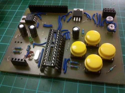
After, a few de-soldering delays I've managed to nearly complete my remote. Tweaked the code, now all four buttons work. Also I've "painted" the backside of the board with nail polish, added some nylon header screws, and a backside made out of xPVC and after dealing with the LCD (de-soldering issues) plugged it in, et voilà. Now I just need to handle battery connection (waiting on JST connectors) and support (will use velcro).


October, 09th 2012
Yet another long evening/night of work (with a lot of distractions and noise) finally led me to a finished assembly of all main TX's components. (Only the LCD and nRF24L01+ modules are not depicted bellow -- they are both pluggable).
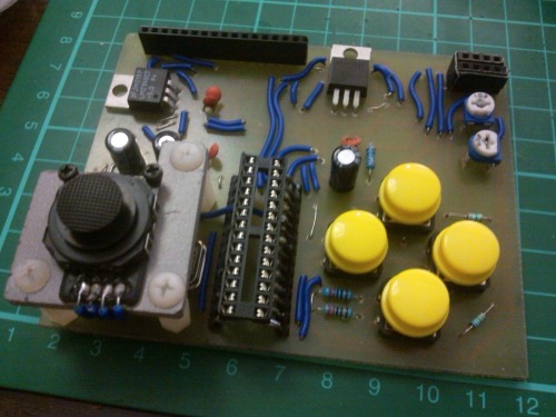
And then I went, for the "smoke test"... first try... no smoke, but also no dice. I've picked up the multimeter and started reading voltages starting at power source. A few minutes in and I've found out that the problem was an Eagle auto-routing fail (plus my own fail of not noticing it before). The only route the the VCC line add after the switch was trough the voltage divider (that I have to gauge battery voltage). A quick soldering of a jumper sorted that out... and yes... it light up! More than that, I've test it further... and surprise surprise it actually worked in controlling a remote RX node (servo + 4 LEDs setup). Now, regarding the TX unit I only need to finish up on the cosmetic details and do some code tweaking (two of the buttons still not registering).

October, 08th 2012
Since last Sunday I've started transfering the board unto a PCB, etching it, drill it (yup still most of the holes were hand-drilled) and finally last night I spent an ungodly amount of hours soldering... all that remains to solder now is 3 ceramic caps and a switch (and then the pin headers when the LCD arrives in the mail. Then I'll add a mount board for the thumbstick and perhaps some cosmetic "cover-ups".
As of the moment the remote control is looking like this:
P.S. - With some help of my soldering iron... I've regressed on my soldering skills (or lack of thereof), so the backside is an ugly mess.
October, 05th 2012
I've been working on designing the TX's PCB on EagleCAD... after a few iterations I got to this... I myself find it butt-ugly, but I think I'll go with this board design. Lot of jumpers on the top side, but couldn't see my way around them. And since I'm doing this as a sort of middle ground between alpha and beta project I think it will suffice.
@ 17:57 UPDATED DESIGN
@ October, 07th Yet another design
@ October, 9th: BEWARE, there are a couple of DESIGN FLAWS here, albeit easily fixable they just make things uglier.
September, 30th 2012
After a (still ongoing) hellish weekend of physical pain and medicine I've managed to reach the desired point of development in my TX unit. It now sends the proper commands to the RX node where those are properly interpreted. Again, and not surprisingly I have to thanks Bajdi for two precious assistances (one indirectly and one direct) that were crucial to jumpstart my progress at two different points during development. The code still needs refining, but for the moment I guess I can divert my full attention to EagleCad and draw the rest of the circuit. Besides Bajdi I want to thank everyone that put up with me in the SB and my whining during this past weekend.

And a video test too: https://www.youtube.com/watch?v=h0thfAE7tCw
September, 27th 2012
Finally, my dear cute nRF24L01+ 2.4GHz radio modules decided it was time to talk to each other. Soon after I've merged Bajdi TX's sample code into my own, I added the thumbstick to my "breadboard remote" and happily sent the tumbstick values to Node 2 (Bajduino RF24 serving as a receptor). I've confirmed the reception of those values using an improv USB-Serial cable and pySerial. (Super easy to work with if you want to get serial data for your costum avr project).
P.S. - On the mechanical side of things, I'm happy with the state of things. Only did a short test, but I got some moderate success when compared with my first secret (and failed) construction attempt. (Yes, that's right. The main reason this part is secret is so that my shame at detailed failure is kept from the public :P)
September, 23th 2012
OK, so far I've been slowly (and mostly silently) developing this project for some time now (about a month, perhaps). But only today did I took a stab at the mechanical part of the vehicule... it did not went very well so I'll say no further.
So basically what I said at the initial announcement of this project still holds true, that is [moved it to blog] for the time being I'm focusing on the Transmiter/Receiver part of the project. I've blogged about it the other day, but since blogs don't get much exposure in LMR I'll create some redundancy here. [removed it now]
NOTE:
Further discussion and/or details regarding the development of the Remote Control part of this project can be found here.
hovers around noisily at my command!
- Actuators / output devices: 9g servo, 1x EDF, 1x brushless motor
- Control method: R/C, nRF24L01+, 2.4GHz radio modules
- CPU: atMega8, atmega328
- Power source: 2-3S LiPo battery 1800 mAh or bigger capacity
- Programming language: Arduino C
- Sensors / input devices: momentary pushbuttons, 2-axis thumbstick, DIY remote control
- Target environment: indoor, outdoor if I want some fresh air