


No name Yet Custom rover
Hi, this is my test platform for my grade project on the University, since the University have a Lynxmotion rover with the AL5D robotic arm and I've already managed to burn the shoulder servo (The big one) and sweep the gears from the little servo for the wrist rotation, I have to paid for the new servo and get metal gears for the little servo instead of the plastic ones, so I decided to built my own to avoid new problems and get a robot tha belongs to ME.
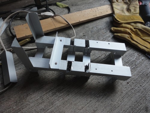
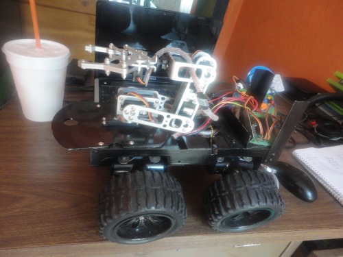
The frame of the rover is made from some aluminium profiles and lots of screws and nuts, as you can seein the next picture
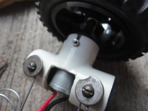
For the motor and wheels I decide to try a suspension method like the one designed by Oddbot in his original wildthumper, so I use some T-shaped pvc parts and and rubber caps, since couldn't get the spiral wire used in the wildthumper suspension, I decide to use the little rods from an old umbrella which I rescue just before the wasa recolected by the trash service.
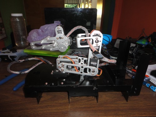
Then I took apart the base from a DAGU robotic arm to mount it on the rover, by the way today I burn the circuit from the servo form the wrist rotation trying to pull a wheeled chair, the arm got stuck with the chair when I tried to move the rover =(, bad luck. Does anybody knows I can replace that servo with a sg90 metal geared or its to small?.
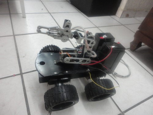
Then I mount the motors and wheels to make it looks more like a rover and less like a robot arm with a big base. this is a picture with some 6v 4a lead acid batteries which I was going to use, but they were to heavy, so I decided to get some lipo batteries fro the motors and ni-mh for the arm.
Then I tested the direccion of the motor's rotation to group them and connected to the sabertooth 2x12 RC motor controller
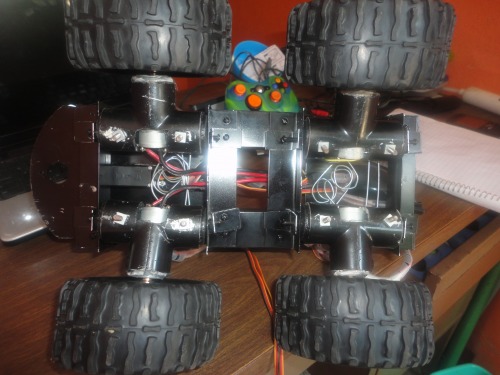
And this is my last picture that correspond to the suspension system seen from below, I personally don´t like it to much but for now its working, I'll change my hand made spirals but like in the Gladiator movie: not yet, not yet.
Today I "finish" the rover that is going to serve like my test platform, and test it with some preliminary code and some extra joystick's that I got to replace the old ones from my xbox 360 control. I couldn´t take photos cause I dont have a proper camera just the VGA without flash from my cellphone (its a very very cheap one), so I ask my sister her camera and maybe tomorrow I'll post some and a video with my rover in the patio. (the code for the client and server node for the arduinos using the nrf24l01 is attached)
For the moment I left a picture from the alpha version of the Java interface to control the arm, since the project just consist on a wireless control for a robotic arm (no rover included), there are another windows like onfiguration of the servos to stablish their limits and dont damage them like I have done before and save or load previos configurations. also exist the principal menu and a record secuence option to be able to record and play secuences for the arm.
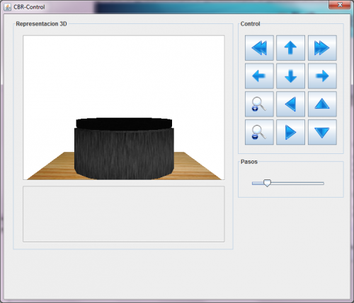
- The left side consist on a 3D representation of the actual position of the arm, right now I jus have draw the base of the lynxmotion arm
- The right top are the button controls with some random icons since I haven't design a proper ones. This are going to work to move each servo individually or using inverse kinematics (not programmed already).
- The right down is a slide to adjust the increments of the angles or miliseconds each time a button is pushed, so the arm can move smothly or as quick as it can.
Navifate via RF
- Actuators / output devices: 6 servos, 4X 1:75 6V Geared Motor
- Control method: wireless Nrf24L01
- CPU: Arduino Mega, Any PC
- Operating system: Arduino, Windows 7
- Power source: 2x 7.4 Volt 2200mA lityum polimer, 6v 2300 mAh NiMH
- Programming language: Java, Arduino C/Wiring
- Target environment: indoor, outdoor