


Nano Sumo (Electronics)
I give you the Nano Sumo bot, a collaborative project between myself and Gary. View Gary's post on Mechanics here
I think this bot "is" many things. Smallest robot using the Arduino bootloader ? Smallest robot with a microcontroller on LMR? Best use of Solarbotics Planetary Gear Boxes?
At the heart of the Nano Sumo is my custom designed micro-controller. It uses a Atmega-328 with a Arduino bootloader programmed into it via the on board ICSP socket. It also has a FTDI programming port for programming it with the Arduino IDE. It measures 21mm x 23mm and has 3 analog inputs, 2 PWM outputs, and 4 I/Os. The PCBs were made by Seedstudio. The Eagle files are available for download here.
The pin layout is designed to mate perfectly with the Sparkfun 1A Dual Motor Driver. The outputs of the Nano’s micro-controller board plug directly into the inputs of the motor controller. This allows for the control of 2 motors with PWM for speed control and breaking. The only other needed connection is a wire providing power to the motor controller.
The power source is provided by a single 50mAh 20C li-poly battery. this provides the system with 4.2v when fully charged and can supply up to 1A. A female connector was added on the end to mate with a male connector on the bottom of the micro-controller and on the charger.
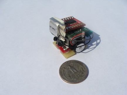
A charger had to be built for this battery. The charger i built uses a Maxim 1555 Li-poly charger IC. It has a LED status light to show that the battery is charging. The charging is powered by a 4 AA battery pack so there is no need to be near a wall outlet to charge. The circuit was completely built on a Sparkfun breakout board (seen as the red PCB in the picture)
There are 2 sensors on the Nano sumo robot. One is an analog reflectance sensor and the other is a digital obstacle detector. The analog sensor is your common line sensor that can sense black and white. This sensor is used to stay in the sumo ring, because if you leave the ring, you lose. The obstacle detector is a very tiny digital sensor that gives either a 1 (no obstacle detected) or 0 (obstacle detected) reading. This is a surface mount sensor that does not come assembled. I soldered it together with no problems, but it was not easy. The sensor has a range of 6 inches, which is just about right for this class of sumo.