


My SHR (Start Here Robot)
Here's my version of the Start Here Robot. It pretty much follows Fritz's directions, with some minor adaptations of the body based on the material I had on hand, and tuning the "clean_navigation" code.
HARDWARE
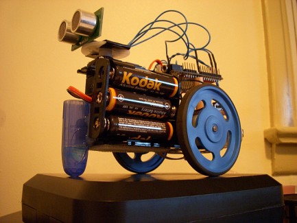
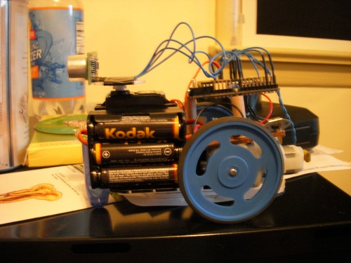
The chassis is made of a plastic electrical connecting block that I had lying around. It is primarily held together with cable ties.
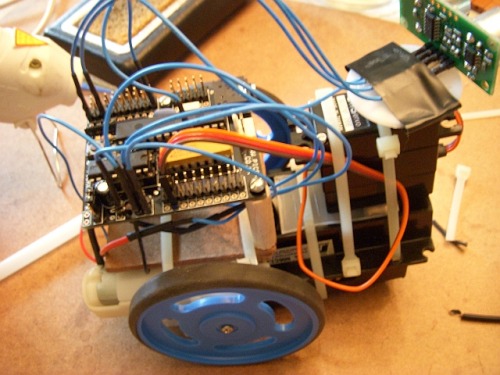
This morning, I made some improvents to the chasis. I mounted the Picaxe board to a little piece of board and some wooden standoffs I made. I had to grind down the diameter of the head of one of the two mounting screws in order to reduce risk of shoring some contacts on the board. It came out looking nicely.
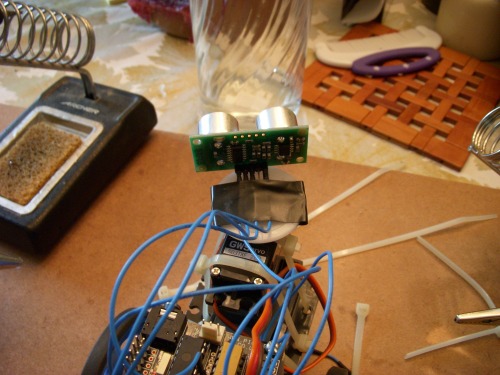
I also added a bit of plastic so the servo mounted level. It used to be cocked slightly upwards.The sensor is mounted on the servo by simply taping the header pins I soldered to the SRF05 to the servo horn.
I also mounted the battery container with separate cable ties. It used to be that to change the batteries, I had to dismount the servo too. While I was at it, I added a little front "foot", which is made from a plastic cable staple with the nail removed. This reduces friction quite a bit.
Lastly, I added a couple of self-tapping screws to better secure the motors to the chassis. Cable ties alone were not working perfectly.
Still to do on the chassis is to re-mount the power switch from the Picaxe board to the mounting board. It is too flimsy where it is mounted to the Picaxe board, and I'm nervous about phyically stressing the Picaxe board with the switch.
The motors are a bit slow and underpowerd with the 4.5V supply. Now that I have some room below the Picaxe board, I may add a separate battery pack for the motors, if I can keep the weight down.
I'm also thinking of adding some LEDs as Left-Turn and Right-Turn indicators, just for fun.
Further Chassis Improvements
- Fle down rear edge of front slider foot; it catches on the floor when reversing
- Flipped left motor so the contacts run to the center, rather than the outside, for better wire management
- Fixed loose power contact and mount power swithc to platform
- Re-routed wires for cleaner management
SOFTWARE
I'm working on tuning the clean_navigation code to this bot. He's pretty small, and with wheels he turns very well on hard surfaces. So I've been slowing shrinking the "red" zone where he looks for obstacles, and decreasing the distance where he starts to back off from an obstacle. I'm not satisfied with his motion yet, but it's getting better.
It's been said before, but I'll say it again. Thanks to Fritz for sharing this code. It provides a HUGE step up for a beginning robot programmer.
TROUBLESHOOTING
I think I may be dealing with noise from the motors or maybe interference with the servo. Maybe both.
To see what's going on, I quickly made an LED test board and hooked it up to three of the outputs on the Picaxe. Then I inserted code to lght the LEDs based on what the software was doing. This way I can see if the robot is behaving as programmed, and also I'll know where in the program he is.
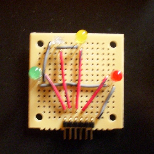
Here's how the LED board should respond to the program.
- Drive Forward = Yellow LED on
- Right Spin = Red LED on
- Right Turn = Red LED and Yellow LED on
- Left Spin = Green LED on
- Left Turn = Green LED and Yellow LED on
- Drive Backwards = Green, Yellow, and Red LEDs all on
Check out the forth video above showing the first LED test drive. What you will notice is that driving forward works as expected (except wihere the bot got hung up on a fold in my carpet mat. Then at about 30 seconds in, the bot reaches the desk and starts freaking out. The LEDs are flashing and I have to rescue the bot by pulling him backwards. You can see the same error about 50 seconds into the video.
At about 1:30 into the video, you can see that backing up works fine (all three LEDs lit).
At about 2:15 into te video, you can see a right turn being commanded by the software (red LED lit), but the bot backs up instead.
My hypothesis is that motor noise is causing this weird behavior. I am going to try:
- soldering 0.1 uF capacitors across the motor contacts
- shortening the length of the motor wires
- twisting each pair of motor wires
- routing the motor wires away from the signal lines
Hopefully I'll see an improvement. Any other advice is certainly appreciated.
Update 2009-07-28
I added a 0.1 uF cap to each motor, shortened the motor wires and twisted each motor wire pair. Performance improved only a tiny bit. There is still something weird going on.
Update 2009-07-29
I looked at the code again and simplified the settings for my LED indicators. Now just two LEDs:
- Green for a left spin or left turn (slide left in Fritz's clean navigation code)
- Red for a right spin or right turn
- Both red and green for backing up
What I see is that the robot gets commanded to turn, but backs up instead. Sometimes he seems to freeze up.
I've also tried disconnecting the servo, with the head and sensor pointed straight ahead. Then I used a piece of cardboard to test his reaction as he approaches the board at different angles. He still appears to have trouble turning most of the time.
Next I tried disconnecting the motors, with the servo re-attached. Now the LEDs provide an indication of what the motors are being told to do. The robot does appear to logically turn left, right or back up according to its programming. I think I may need to do more about noise reduction of the motors. Either additional capacitors or a separate battery pack for the motors.
Update 200-07-31
I made several more improvements to the chassis.

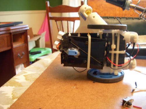
Replaced cable staple front foot with a pencap hot glued to the front and moved battery pack from under bot to next to servo for better ground clearance.
Eliminated cable ties holding battery pack and servo in place. The battery pack is now attached with hook and loop. The servo is attached with hot glue (seems to be a favorite technique here at LMR). I also replaced screwe holding motors to chassis with longer ones; easier to align motors.
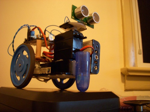
There's room on the right side of the head servo to add another servo, for an arm, drum stick, who knows? Or I could stick a speaker there or some sort of display.
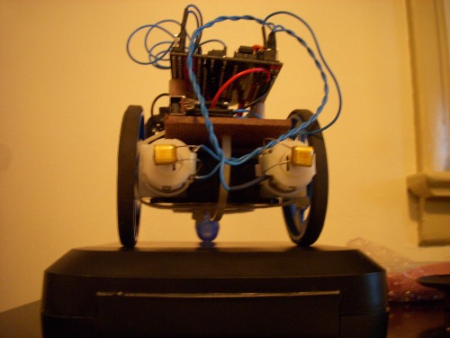
In this rear view you can see the little film capacitors I bought because the local electronics shop didn't have 0.1 uF ceramic discs in stock. I paid too much for them. They look kinda cool, though.
I'm pretty happy with all these changes.The old foot used to catch on things when backing up. The bot used to sit with its front end slightly higher than the rear; it is now level, and the pencap foot has very little surface area touching the ground. Overall this is a much better platform now.
I did notice that the left motor runs significantly faster than the right, so the bot pulls strongly to the right when moving forward. I've read on this site that this is pretty common. On a bot this simple (no wheel encoders, no dfferential) there's not much I can do to correct it.
I don't recall the problem being this bad before I added the capacitors. I wonder if there is some way the capacitors could have affected motor speed. I guess I could try removing the caps to see if they are causing this somehow. The caps are identical type and both are 0.1 uF.
I also read Oddbot's comments elsewhere on this site that small DC motors tend to run slower in one direction than in the other. This led me to try swapping the connections on the slower right motor and adjusting my code accordingly. I was pretty excited and thought this might do the trick, but it had no noticable affect.
I also greatly simplified the bot's navigation code, and he gets around fairly well now. He is a bit aimless. Time to start building some more interesting behavior into him.
Update 2009-07-31
Looking back at the videos, I can see that SHR used to drive pretty straight. This is very obvious at the beginning of the forth video.
I was contemplating trying PWM to compensate for the differnece in motor speeds, but now I think I need to go back and see what changed.
Update 2009-08-02
Good news! I found one of the right motor connections was a bit loose. It wasn't makeing perfect contact, and that's why the motor was so slow. Now that I've fixed that, he drives pretty straight again. Not perfect, but completely acceptable.
Update 2009-08-18
I think it is time to call this bot complete. I made several improvements:
- Upgraded from 3 AA to 4 AA batteries
- Added a 5V voltage regulator with 6V pass through for the motors and servo
- Re-mounted the project board more securely and integrated the voltage regulator below
- Added a small piezo speaker for sound effects
This was a good learning experience. I will keep this bot around for a while so I can work on programming techniques. Maybe I'll add some new features if I need to test something out.
Navagates around and avoids stuff.
- Actuators / output devices: 2 Gear Motor 9 from Hobby Engineering, Gear Motor Upgrade, JR S03TXF Servo for sensor positioning, Ball Bearing upgrade to servo
- CPU: Picaxe 28x1
- Power source: 5v regulator, 4 AA cells, 6V pass-through for motors and servo
- Programming language: Picaxe basic
- Sensors / input devices: SRF05
- Target environment: Indoors - hard floor